www.DaikinApplied.com 37 IM 817-7
Unit Ventilator Split Systems
Guidelines
The following provides basic guidelines that will provide
proper system cooling and operation of an R-410
commercial DX/hot water system for school applications.
DX system components must be matched and sized
correctly (not oversized) for the load.
The DX system must incorporate the following, provided
by others, for proper operation:
• Size piping per ASHRAE Refrigeration Handbook
(correct refrigerant and compressor oil ow), see
Table 31 on page 38.
• Use clean sealed refrigerant grade piping (prevent
system contamination)
• Install Liquid Line Filter Dryer (clean/dry system to
prevent damage of operating components), see Figure
97 on page 38.
• Install Liquid Line Sight Glass (indicates refrigerant
dryness and if liquid in liquid line - do not use the
sight glass to determine when refrigerant system is
charged correctly), see Figure 97 on page 38.
• Install pressure taps on the unit ventilator’s liquid
line and suction lines for subcooling and superheat
measurements at the unit ventilator, see Figure 97 on
page 38.
• Install High Pressure Switch at condensing unit wired
in condenser control system (protects compressor
and refrigerant system from excessive pressures -
condenser fan failure or overcharging), see Figure 98
on page 39.
• Install Low Pressure Switch at condensing unit wired in
the condenser control system (low refrigerant pressure
switch protects the system under low refrigerant
suction conditions), see Figure 98 on page 39.
• Install Low Ambient Temperature Switch at
condensing unit wired in the condenser control
system (locks out mechanical cooling below 60ºF -
proper system operation and free economizer usage),
see Figure 98 on page 39.
• Incorporate Compressor Time Delay (5 minute) in
condensing unit control system (reduces excessive
compressor cycling), see Figure 98 on page 39.
• Single phase compressors - consider hard start kits to
overcome non-equalized pressure in refrigerant lines.
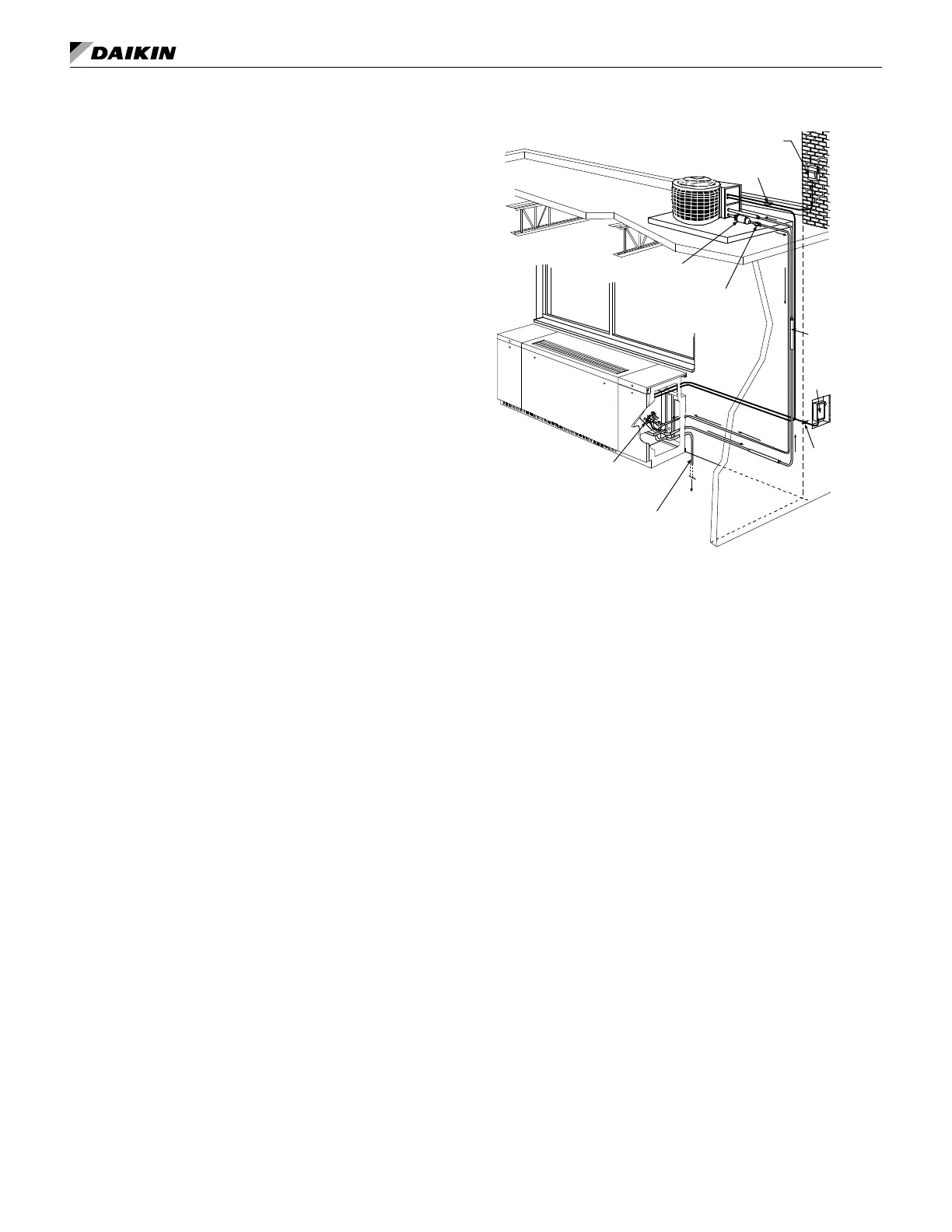
Figure 95: Typical Piping and Wiring for Split System
2 Wires (+) Ground
To Open Sight Drain
TXV
(Thermal Expansion
Valve)
Filter Drier (Field Supplied)
Moisture Indicator Sight
Glass (Field Supplied)
Weatherproof Fused Disconnect Per NEC
2 Wires
(+) Ground
Insulated
Suction Line
Fused
Disconnect
• Incorporate Low Refrigerant Temperature Sensor
(T4) in condensing unit control system (T4 protects
the system under low refrigerant suction conditions)
see Figure 98 on page 39.
• UV fans must continue to run upon Low Refrigerant
Temperature trip of T4 (controls by others) or ICT
(MicroTech) (evaporator air ow dissipates residual low
coil surface temperatures - suction pressures raised, coil
frosting reduced), see Figure 98 on page 39.
• UV fans must continue to run for set time period
during unoccupied mode after satisfaction of the
space sensor (dissipates residual low evaporator coil
surface temperatures - reducing coil frosting), see
Figure 98 on page 39.
• Lock the Face and Bypass Damper (actuator spring
return to full face when de-energized) in the full face
position during mechanical cooling (full air through
evaporator coil reduces low refrigerant suction
conditions, potential coil frosting)
• When Brazing bleed Nitrogen through piping
(reduced oxides and blockage in piping/TXV)
• Use Heat Sink when brazing to prevent overheating
the TXV valve body and bulb (avoid valve damage
and erratic operation), see Figure 94 on page 36.
• Verify the TXV bulb securely attached at 2 or 10
o’clock for 7/8" and smaller diameter suction line
piping (proper suction gas sensing and reduced
hunting) See Figure 94 on page 36.
• Insulate the TXV bulb (reacts to refrigerant
temperatures and not ambient), see Figure 96.