IM 817-7 58 www.DaikinApplied.com
Controls by Others - Variable
Airow
An optional EC motor with “variable fan speed control”
allows a eld provided DDC controller to modulate the
unit airow between 50% and 100% of nominal unit
airow in a single zone variable air volume sequence.
In continuous fan mode the benets of Single Zone VAV
include sound reduction, energy savings, and consistent
and precise temperature control for improved comfort
with better air mixing and less stratication. In humid
climates, the ability to deliver a wide range of fan speeds
is particularly effective for de-humidication.
Note: This option is not available with MicroTech controls.
Making Control Connections
For eld provided control wiring connections refer to the
appropriate control wiring schematic, page 59 or page
60.
Connect the eld supplied controller to the harness
provided. A 0-10VDC fan control signal must be provided
between ground and wire 33. For RPM/data out signal,
connect controller to wire 34.
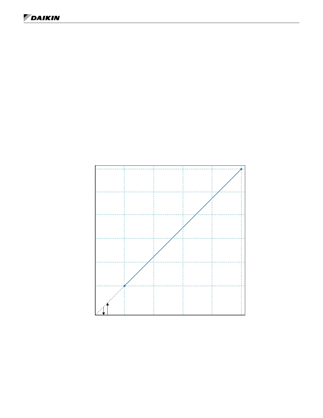
The variable fan speed scale is linear between a
minimum 50% airow at 2vdc and a maximum 100%
airow at 10vdc as shown in Figure 120. Reducing the
input signal to 0vdc will cause the motor to turn off. Care
should be taken when using variable airow on units with
DX cooling as lower airow may increase the risk of coil
freeze-up. Variable airow control should not be used on
units with electric heat.
Figure 118: 0-10VDC Variable Fan Speed Control
10
100
8426
50
60
70
80
90
0-10 VDC Control Signal
0