Indoor Unit SiBE041102_A
116 Removal Procedure
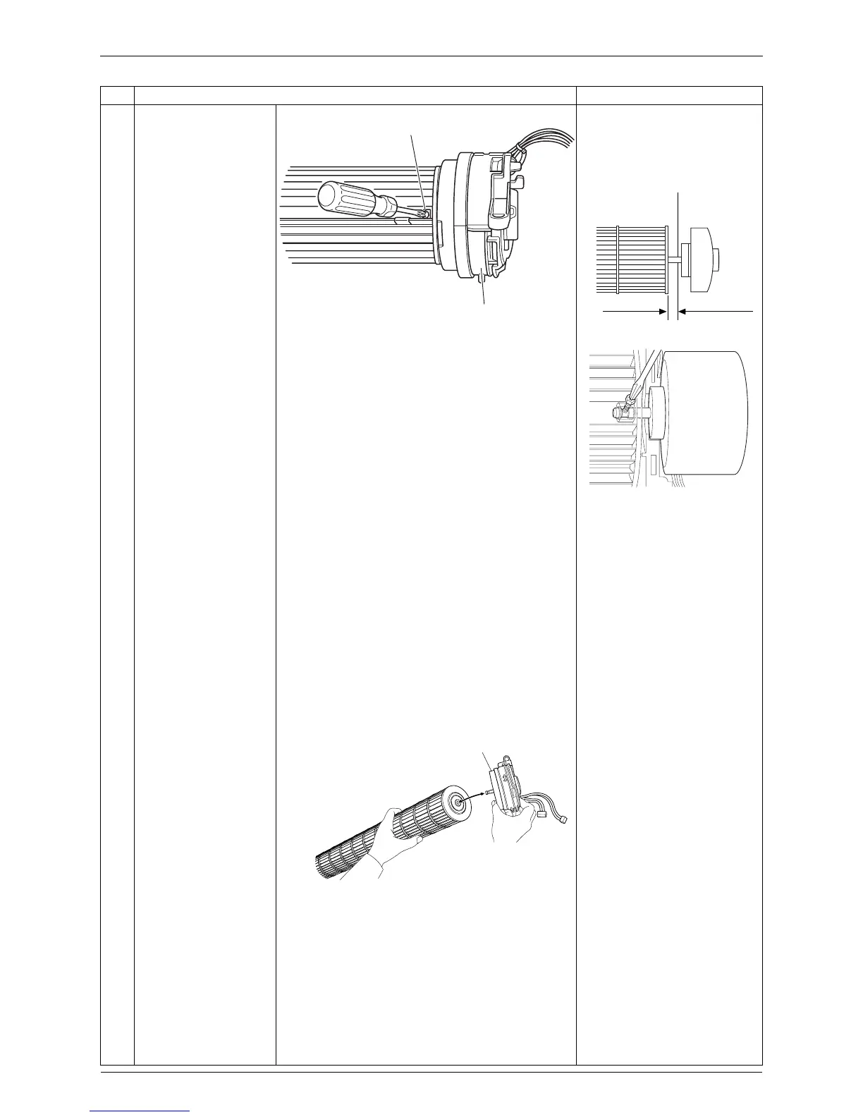
5
Loosen the lock screw
and remove the fan
motor.
When reassembling the fan
rotor, provide as much as
5 mm of play between the
side face of the rotor and the
bottom frame.
(1) Insert the fan motor with
approx. 5 mm left.
(2) Tighten the screw until it
stops. Then turn the screw
in one scroll.
(3) Move the fan rotor and
confirm the fan motor and
the fan rotor are installed
appropriately.
(4) Tighten the screw
completely if appropriate.
(5) If not appropriate, go back to
(1).
6
Pull out the fan motor
from the fan rotor.
Step Procedure Points
(R14544)
Lock screw
Fan motor
(R2808)
Side face of rotor
Side face of
bottom frame
5 mm
(R9582)
Fan motor
(R14543)
 Loading...