1.
2.
3.
4.
5.
BA C D E
Danfoss
84B8332
X
AKV
Figure 14: Defrost start
Network:
The defrost start signal is received from a system manager via data communication.
Max. thermostat runtime:
When the aggregate time has passed a preset value, a defrost will be initiated.
Manual:
An extra defrost can be activated from the defrost button on the AK-UI55 Set display or via a parameter setting. All
the mentioned methods can be used in parallel – if just one of them is activated, a defrost will be started.
Stop of defrost
Defrosting can be stopped by either:
• Time
• S4 temperature (with time as safety)
• S5 temperature (with time as safety)
When the selected defrost stop sensor reaches the set defrost stop limit, the defrost is terminated. If the defrost stop
sensor does not reach the set defrost stop limit within the set max. defrost time, the defrost will be terminated on
time.
Defrost sequence
When a defrost is initiated, the controller will run through the following sequence:
Pump down: where the evaporator is emptied of refrigerant
Defrost: where the ice on the evaporator is melted
Hold after defrosting: where multiple controllers wait for each other (coordinated defrost)
Drip o: where remaining water is dripping o evaporator
Fan delay: where the fans are restarted when the remaining water on the evaporator has turned into ice
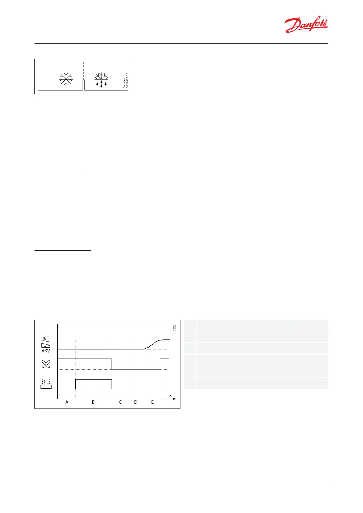
Figure 15: Electrical defrost sequence
During an electrical defrost sequence where the defrost heater is ON during defrost, AKV valve is closed and fans are
running during defrost but stopped during drip.
Fan control during defrost
During the defrost sequence, the evaporator fans can be controlled in one of the following ways:
AK-CC55 Multi Coil
© Danfoss | Climate Solutions | 2022.08 BC365022028193en-000201 | 14