The signal from one pressure transmitter can be received by up to 10 controllers. There must not be a signicant
pressure drop from the pressure transmitter's position in the suction line to the individual evaporators.
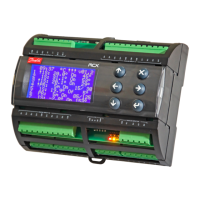
Coordinated defrost via cable connections
Figure 40: Coordinated defrost via cable connections
Max. 10
The following controllers can be connected in this way:
EKC 204A, AK-CC 210, AK-CC 250, AK-CC 450, AK-CC 550 and AK-CC55.
Refrigeration is resumed at the same time when all controllers have terminated defrost.
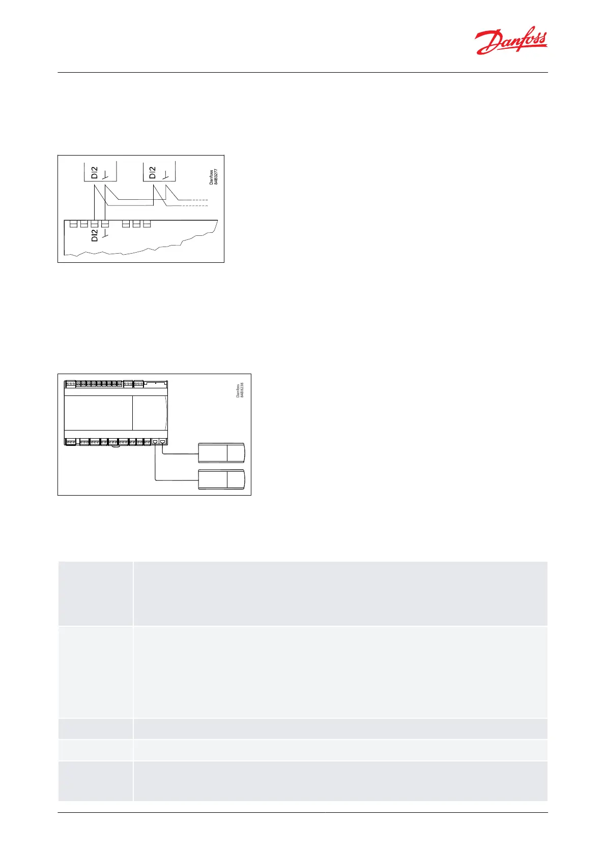
External display AK-UI55
Figure 41: External display AK-UI55
(Total length: max. 100 m)
Connections
Table 11: Connection details
Pressure transmitter
AKS 32R
Connect to terminal 40, 41 and 42.
(Use cable 060G1034: Black=40, Brown=41, Blue=42)
The signal from one pressure transmitter can be received by up to 10 controllers. But only if there are no signicant pressure drops be-
tween the evaporators to be controlled. See Figure 39: AKS 32R info.
Primarily for temperature inputs
• S2
Pt 1000 ohm sensor AKS11, placed at the evaporator outlet
• S4, S5
Pt 1000 AKS11, PTC 1000 EKS111, NTC5K EKS211 or NTC10K EKS221 sensor or a user-dened sensor type. All have to be of the same
type.
• S4, discharge air sensor, placed in the cold air of the evaporator
• S5, defrost sensor, placed in the evaporator.
•
RH%, 0 – 10 V signal input from Humidity sensor
(If the DI1 input is used for a temperature measurement, it will appear as AI7.)
Digital input signal (dry contact)
The dened function is active when the input is short-circuited or opened, depending on the function dened in o02.
Digital input signal (dry contact)
The dened function is active when the input is short-circuited or opened, depending on the function dened in o37.
Analogue output signal
• Analogue 0 – 10 V (currently not used)
• Pulse width modulated signal
Can be used for fast pulse control of rail heat via an external power solid state relay.
© Danfoss | Climate Solutions | 2022.08 BC365022028193en-000201 | 27
AK-CC55 Multi Coil