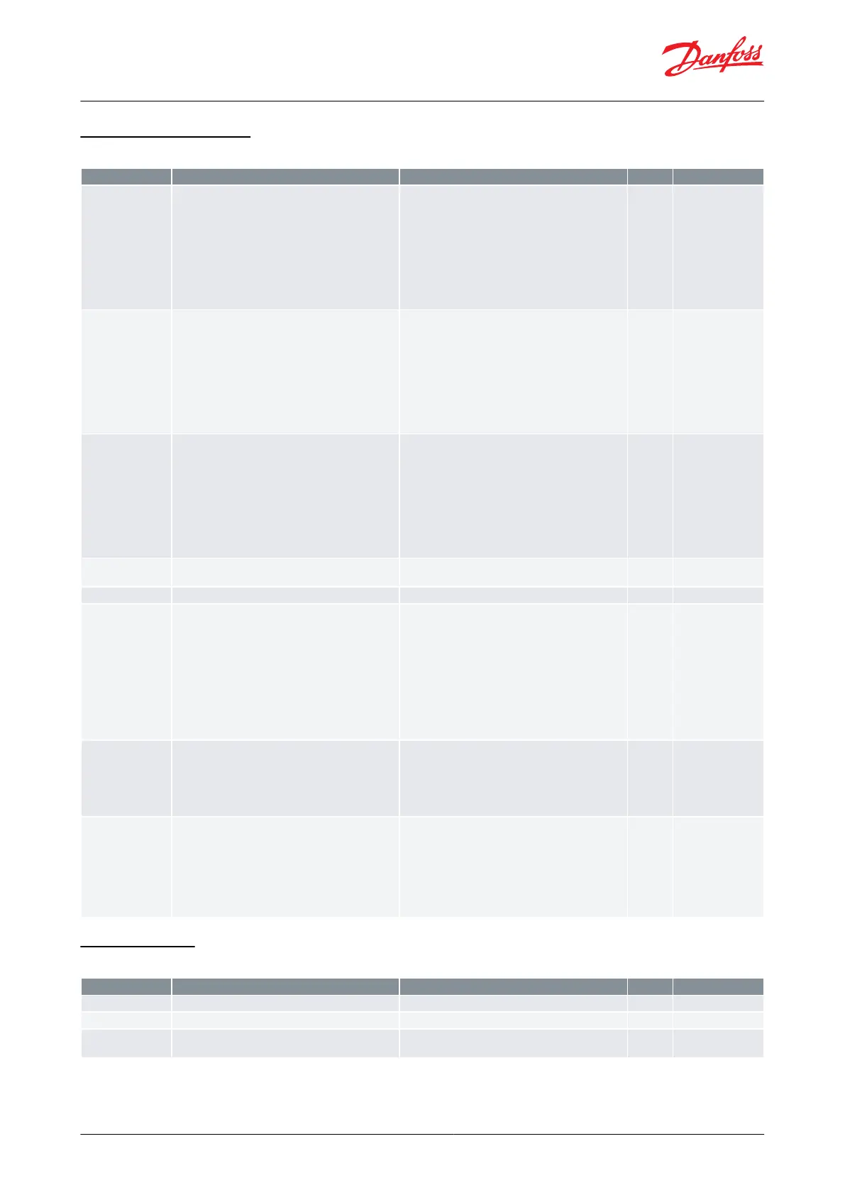
Light/Cleaning control
Table 37: Light/Cleaning control
Readout of the actual control state of the controller
0=Normal ctrl., 1=Hold after defrost, 4=Drip o,
10=Main switch OFF, 11=Thermostat cutout, 12=Frost
protection S4, 13=Not_used, 14=Defrost, 15=Fan de-
lay, 16=Forced closing, 17=Door open, 18=Melt peri-
od, 19=Modulating temp. control, 20=Emergency
control, 23=Adaptive superheat control, 24=Start in-
jection, 25=Manual control, 26=No refrigerant selec-
ted, 29=Case cleaning, 30=Forced cooling, 31=Door
open, 32=Power-up delay, 33=Air heating, 45=Shut
down controller, 48=Adaptive liquid control
Status of the day/night operation (night operation:
on/o)
Actual status of output function
Conguration of light function
1: Light is controlled via day/night status
2: Light is controlled via data communication and
master control parameter "MC Light signal"
3: Light is controlled by door contact on DI input.
When the door is opened the relay will cut in. When
the door is closed again there will be a time delay of
two minutes before the light is switched o.
4: As "2" but if there are any 15-minute network errors,
the light will switch on and the night blind will open.
5: Light is controlled via DI input signal
1=Day and night, 2=Network, 3=Door switch, 4=Net-
work (Fallback), 5=Digital input
Dene how light and blinds are to be controlled at
Main switch OFF
0: Light is switched o and night blinds are open
when the main switch is o
1: Light and night blinds are independent of main
switch.
The status of the function can be seen here or the
function can be started manually.
0 = Normal operation (no cleaning)
1 = Only fans are running to defrost the evaporator.
All other outputs are O.
2 = Cleaning with stopped fans. All outputs are O. If
the function is controlled by a digital input signal, the
relevant status can be seen here in the menu.
0=OFF, 1=Fans run, 2=Cleaning
Display control
Table 38: Display control
Readout of the temperature shown on the display
Readout of the temperature shown on the display
Select which temperature to show in the display
1=Ther. air A, 2=Average all, 3=Maximum all, 4=S4A
and S4B
© Danfoss | Climate Solutions | 2022.08 BC365022028193en-000201 | 53
AK-CC55 Multi Coil