2.8 Heat pump control panel
The heat pump control panel consists of a display, four control but-
tons and an indicator.
Display, control buttons and indicator for the heat pump.Figure 21:
The control computer is controlled using a user-friendly menu sys-
tem, displayed in the display.
Use the four control buttons to navigate the menus and increase or
reduce the set values:
• Anupbuttonwithaplussign
• Adownbuttonwithaminussign
• Arightbuttonwitharightarrow
• Aleftbuttonwithaleftarrow
The main menu, INFORMATION, is opened by pressing the left or
right buttons. From INFORMATION one of the four sub-menus can
be opened: OPERAT.; HEATCURVE; TEMPERATURE and OPERAT. TIME.
For installation or service, the hidden menu, SERVICE, is used. This
is opened by holding the left button depressed for five seconds.
From the SERVICE menu one of the following sub-menus can be
opened: WARMWATER; HEATPUMP; ADD.HEAT; MANUAL TEST and
INSTALLATION.
For further information about the menus see the service instruc-
tions.
The indicator at the bottom of the control panel has two modes:
• Litsteadily,theinstallationhaspowerandisreadytoproduce
heat or hot water
• Flashing,meansanactivealarm
2.9 Transporting the heat pump
The heat pump must always be transported and stored upright.
Secure the heat pump so that it cannot tip over during transporta-
tion.
When transporting indoors to the installation location it may be
necessary to place the heat pump on its back. The time that the
heat pump is transported on its back should be as short as possible.
After the heat pump has been lifted up again it must stand upright
for at least an hour before commissioning.
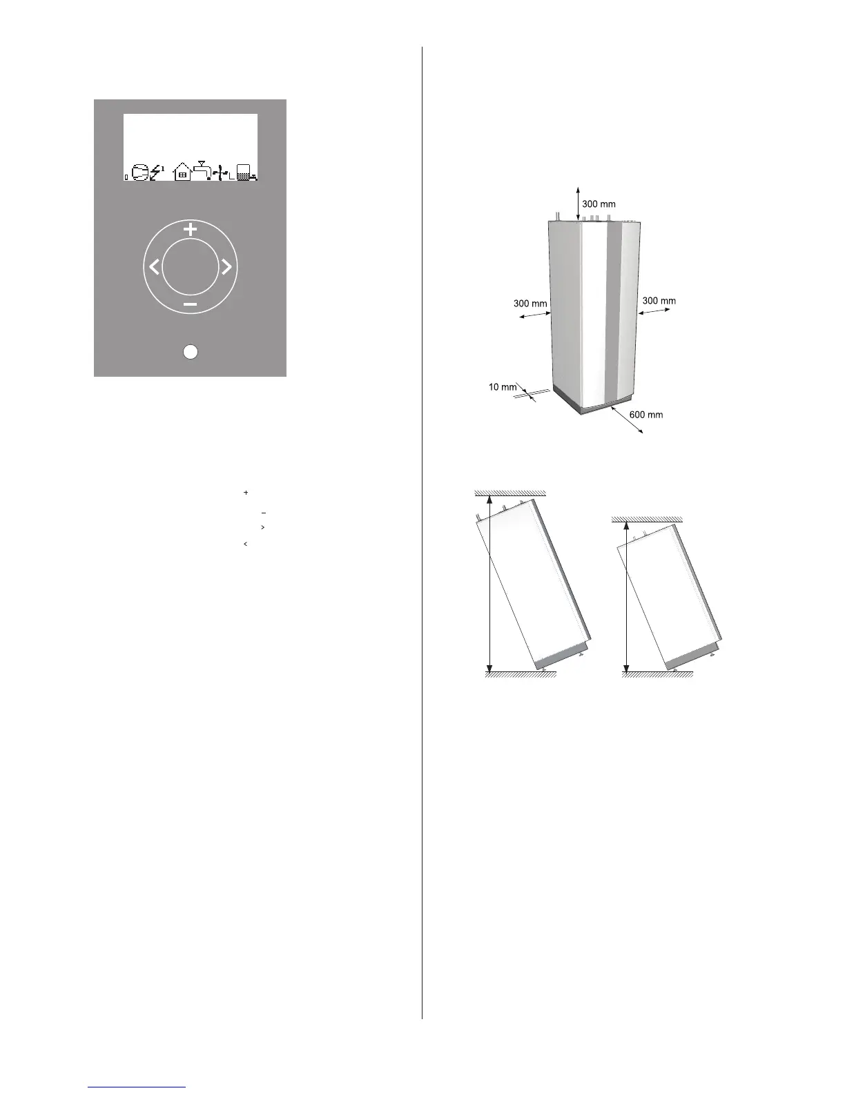
2.10 Space requirement
To facilitate the installation and subsequent testing and mainte-
nance it is recommended that there is sufficient free space around
the heat pump in accordance with the following dimensions:
– 300 mm on each side
– 300 mm above
– 600 mm in front
– 10 mm behind
Necessary service space.Figure 22:
Minimum headroom for heat pump installation.Figure 23:
2.11 Recommended location
⚠
To avoid condensation problems for the brine pipes, as short
a brine pipe as possible is recommended.
The heat pump should be located on a stable floor, preferably
made of concrete. When locating the heat pump on a wooden floor
this should be reinforced to take the weight. One solution is to
place a thick metal plate, at least 6mm, under the heat pump. The
metal plate should cover several joists spreading the weight of the
heat pump over a larger area. If the heat pump is being installed
in a newly-built house, this has normally been taken into account
during construction, and the joists where the heat pump will be
located have been reinforced. Always check that this has been car-
ried out when installing into a newly-built house. Avoid positioning
the heat pump in a corner as the surrounding walls may amplify its
noise. It is also important to adjust the heat pump using the adjust-
able feet so that it is horizontal to the base.
The symbols in the display are
only examples. Certain sym-
bols cannot be displayed at
the same time.
ROOM
20°C
(20°C)
NO DEMAND HEAT
OPERAT. AUTO