DHP-AL:
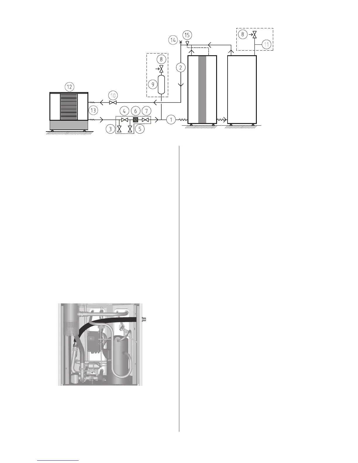
Connection diagram for brine pipes. Figure 69:
Position Name
1 Brine in
2 Brine out
3 Shut-off valve (part of the filler cock)
4 Shut-off valve (part of the filler cock)
5 Shut-off valve (part of the filler cock)
6 Strainer (part of the filler cock)
7 Shut-off valve (part of the filler cock)
8 Safety valve (1.5 bar)
9 Bleed and expansion tank
10 Shut-off valve
11 Pressure tank
12 Outdoor unit
13 Flexible hoses
14 Bleed valve
15 Moved out supply line sensor, brine
8.6 Installing brine pipes
1. Determine to which side the brine pipes are to be connected.
2. Route the out pipe for brine in through the corresponding hole
(with rubber collar) in the heat pump side.
3. Install all necessary components on the pipe.
Remember to install the filler cock with the filter cover upwards.
4. Route the out pipe for brine out through the corresponding
hole (with rubber collar) in the heat pump side.
⚠
When the brine lines are connected to the right for DHP-A,
the brine out line must be routed over the brine pump, under
the compressor’s vacuum pipe and under the condenser’s
flexible hose, see figure below.
Routing of pipes for brine out for DHP-A. Figure 70:
5. Install the out pipe with all the accompanying components.
6. Install the expansion tank with the safety valve.
7. Fit both brine pipes with anti-diffusion insulation running all
the way from the heat pump to the lead-in in the wall. The
brine pipes running outside the house to the collector can be
buried, however they must be well insulated.
⚠
Applies to DHP-A, -AL: Bear in mind that the outdoor unit
may move during defrosts, use flexible hoses to connect the
pipes from the heat pump and pipes on the outdoor unit.
8.7 Filling the brine system
⚠
NOTE! Before filling the brine system, the electrical installa-
tion must be completed so that it is possible to operate the
brine pump.
⚠
NOTE! Before filling the brine system for DHP-A, -AL, the
water heater MUST be filled.
⚠
NOTE! Always check local rules and regulations before using
anti-freeze.
⚠
NOTE! Anti-freeze with corrosion protection additives must
be used and mixed to achieve frost protection down to -15°C
for models Diplomat and Comfort.
⚠
NOTE! Use only ethylene glycol as anti freeze for DHP-A and
DHP-AL, mixed to achieve frost protection down to -32°C.
Calculated volume, DHP-H, -C, -L
The volume of the brine system is calculated as follows:
• Heatpump(exchangerandpiping)approximately2litres
• Expansiontankapproximately3litres
• Collector(singlepipe):PEM40approximately1.0litre/m;PEM32
approximately 0.6 litre/m; Cu 28 approximately 0.5 litre/m
Calculated volume, DHP-A, -AL
The volume of the brine system is calculated as follows:
• Heatpump(exchanger,pipeandouterjacket)approximately47
litres
• Expansiontankapproximately3litres
• Outdoorunitapproximately7litres
• Collector(singlepipe):28mmpipeapprox.0.5litre/m
Heat pump Water heater
If the outdoor unit is installed
higher than the heat pump
the expansion outlet must be
used together with a pres-
sure tank.
If the outdoor unit is installed at the same
level or lower than the heat pump, the
accompanying plastic vessel can be used.
The upper part of the outdoor unit must
then not exceed the fluid level in the
vessel.