6.7 Filling the water heater and heating sys-
tem
1. Fill the water heater with cold water by opening the filler valve
(10) which is located on the valve pipe.
2. Bleed by opening one of the hot water taps.
3. Then fill the water heater coil and the heating system with
water through the filling valve (12) to a pressure of approx. 1
bar.
6.8 Bleeding the heating system
1. Open all radiator valves fully.
2. Bleed all radiators.
3. Refill the heating system to a pressure of approximately 1 bar.
4. Repeat the procedure until all air has been removed.
5. Leave the radiator valves fully open.
7 Electrical Installation
⚠
Electrical current! The terminal blocks are live and can be
highly dangerous due to the risk of electric shock. The power
supply must be isolated before electrical installation is start-
ed. The heat pump is connected internally at the factory, for
this reason electrical installation consists mainly of the con-
nection of the power supply.
• Electricalinstallationmayonlybecarriedoutbyanauthorized
electrician and must follow applicable local and national regula-
tions.
• Theelectricalinstallationmustbecarriedoutusingpermanently
routed cables. It must be possible to isolate the power supply
using an all-pole circuit breaker with a minimum contact gap of 3
mm. (The maximum load for externally connected units is 2A).
• Electricalconnectioncanalsocausenoisesothisinstallation
must be carried out appropriately. The figure below shows an
appropriate installation. There is approximately 300mm free
cable between the heat pump and building, however, this
requires the cable to be securely installed onto the top panel so
that the cable cannot be fed into the heat pump. It is inappropri-
ate to bolt trunking between the heat pump and the wall. This is
because vibrations can then be transmitted from the heat pump
through the trunking to the walls of the house.
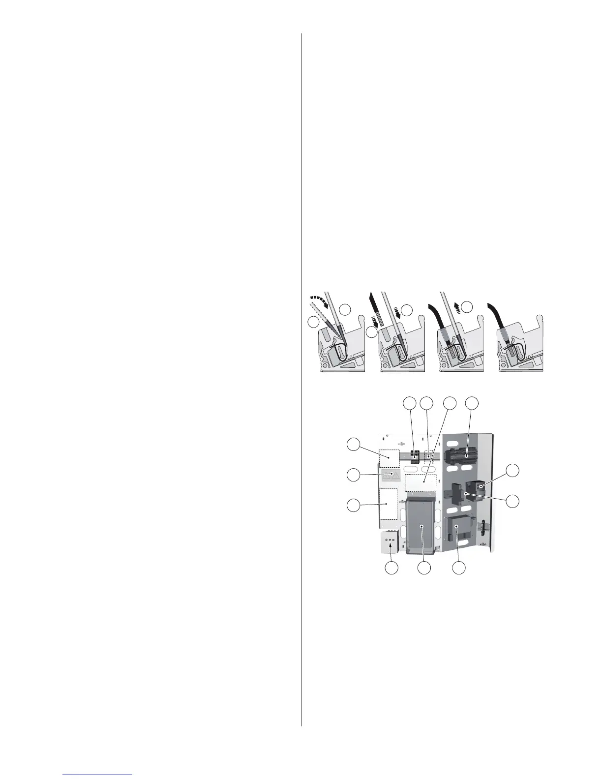
• Whenthecableisconnectedtotheterminalblockascrewdriver
is used to open the terminal block, see figure below.
Connecting cable to terminal block. Figure 54:
The location of the components on the electrical panel.Figure 55:
Position Name
1 Terminal block (applies to the expansion card)
2 Terminal block (applies to DHP-A, -AL)
3 Defrost card (applies to DHP-A, -AL)
4 Terminal block
5 Space for Danfoss Online
6 Warning decal
7 Space for expansion card
8 Contactor for compressor
9 Automatic fuses
10 Resetting overheating protection
11 Control computer
12 Soft starter card