9 Installing accessories/additional
functions
9.1 Room temperature sensor
The room temperature sensor has a temperature sensor that
provides a further value that the control computer can use when
calculating the supply temperature. The influence of the room sen-
sor in the calculation can be set in the menu HEAT CURVE-> ROOM
FACTOR. Default setting for ROOM FACTOR is 2 but can be adjusted
from 0 (no impact) to 4 (large impact).
The difference between the desired and actual indoor temperature
is multiplied by the set value for ROOM FACTOR. The set point on
the heating system’s supply line increases or decreases with the
result depending on whether there is a deficit or surplus of heat.
The table below shows examples of how the set point for the sup-
ply line is affected at CURVE 40 with different settings for ROOM
FACTOR.
In the event of a heating deficit:
ROOM
FACTOR
Desired room
temperature, °C
Actual room
temperature, °C
Set point for
supply line, °C
0 22 20 40
1 22 20 42
2 22 20 44
3 22 20 46
4 22 20 48
In the event of a surplus of heat the conditions are the opposite:
ROOM
FACTOR
Desired room
temperature, °C
Actual room
temperature, °C
Set point for
supply line, °C
0 20 22 40
1 20 22 38
2 20 22 36
3 20 22 34
4 20 22 32
⚠
NOTE! The room temperature sensor is connected to a safety
extra-low voltage.
1. Install the room temperature sensor in a location in the house
where the room temperature is relatively constant:
• Centrallylocatedinthehouse
• Ateyelevel
• Notindirectsunlight
• Notinadraft
• Notinaroomwithalternativeheating
2. Hang a thermometer next to the room temperature sensor in
order to calibrate it after connecting it.
3. Connect the room temperature sensor to terminal blocks 303
and 304.
4. After connecting the room temperature sensor, it is calibrated
by holding in both buttons for 15 seconds until the display
starts to flash.
5. Set the actual room temperature that the thermometer shows.
6. Wait 10 seconds until the display stops flashing.
If the display shows “--” for outdoor temperature no outdoor tem-
perature has been read.
9.2 EVU function
The EVU function prevents the operation of HEATPUMP, ADD.HEAT
and CIRC.PUMP as long as the contact is closed. The text EVU STOP
is shown in the display when this function is active.
• TheEVUfunctionisactivatedbymakingaconnectionbetween
terminal blocks 307 and 308 using an external 1-pin timer.
9.3 Tariff control
The room temperature lowering function provides a regular, tem-
porary lowering of the indoor temperature.
• Thetariffcontrolisactivatedbymakingaconnectionbetween
terminal blocks 307 and 308 using an external 1-pin timer and a
10 kohm resistor.
• Theextenttowhichthetemperatureisloweredissetinthe
menu INFORMATION -> Heatcurve -> REDUCTION.
9.4 Flow switch/level switch
In certain countries there is a requirement that the heat pump must
be equipped with a level switch for the brine system. Always check
local rules and regulations before commissioning the heat pump.
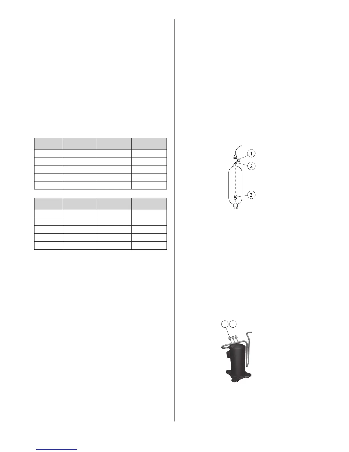
Level switch in the expansion tank/bleed tank.Figure 74:
Position Name
1 Safety valve
2 Level switch
3 Floats
• Connecttheflowswitchorlevelswitchtoterminalblocks217
and 219.
9.5 Higher hot water temperature
⚠
Does not apply to models with refrigerant R134a, models
DHP-C -4H, -5H and -7H.
⚠
NOTE! Never connect the heat pump to provide a higher
temperature unless the heating or hot water systems require
it. Higher temperatures increase the load on the heat pump.
If necessary, the heat pump can be connected to produce hot-
ter water for the heating system and hot water system when it is
installed.
The pressure switches on the compressor’s pressure pipe.Figure 75:
1. Move the grey cables, which are normally connected to pres-
sure switch A, to pressure switch B.