5
VMBMA602
1
1
2
3
4
5
6
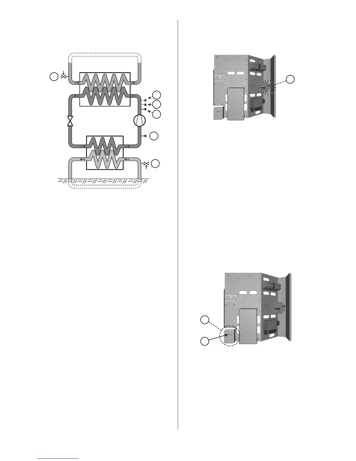
Heat transfer circuit
Refrigerant circuit
Brine circuit
1.4 Control and safety devices
To ensure a correct function of the heat pump there are a number
of control and safety devices.
The figure below shows the heat pump’s three liquid circuits with
respective safety function.
Control and safety devices.Figure 1:
Position Name
1 Safety valve, heat transfer circuit, external mounted.
2 Pressure switch, operation, 2,65 MPa
3 Pressure switch, operation, 2,85 MPa
4 Pressure switch, high pressure, 3,10 MPa
5 Pressure switch, low pressure, 0,08 Mpa
6 Safety valve, brine circuit, external mounted.
Heat transfer circuit
If the pressure in this circuit exceeds the opening pressure of the
safety valve (1), the valve opens to release the overflow and then
shuts again. The safety valve overflow pipe must have an open con-
nection to the drain and visibly flow into this in a frost-free environ-
ment.
Refrigerant circuit
The refrigerant circuit’s high pressure side is equipped with a high
pressure switch (4) and two operational pressure switches (2,3)
(only one is connected). The connected operational pressure switch
stops the compressor when the switching point is reached, that is,
when sufficient amount of heat is produced.
If the operational pressure switch should fail and the pressure
continue to rise, the compressor is stopped by the high pressure
switch when its switching point is reached. The operation of the
heat pump is blocked. When the problem with the abnormally high
pressure is solved, the pressure switch is automatically reset.
If the high pressure switch is tripped the alarm indicator on the
front panel is flashing and an alarm text is displayed. Restart the
heat pump by first setting the operational mode to OFF and then
back to previous mode (AUTO/HEATPUMP/ADD.HEAT/HOT WATER).
The low pressure switch (5) stops the compressor if the pressure is
too low on the low pressure side. The operation of the heat pump
is blocked. When the problem with the abnormally low pressure is
solved, the pressure switch is automatically reset.
If the low pressure switch is tripped the alarm indicator on the front
panel is flashing and an alarm text is displayed. Restart the heat
pump by first setting the operational mode to OFF and then back
to previous mode (AUTO/HEATPUMP/ADD.HEAT/HOT WATER).
Brine circuit
If the pressure in this circuit exceeds the opening pressure of the
safety valve (6), the valve opens to release the overflow and then
shuts again. The safety valve overflow pipe must have an open con-
nection to the drain and visibly flow into this in a frost-free environ-
ment.
Compressor
The compressor is equipped with a thermal overload relay which
protects the compressor from over current.
The thermal overload relay on the electrical panel.Figure 2:
Position Name
1 Thermal overload relay (F11)
If the thermal overload relay is tripped the alarm indicator on the
front panel is flashing and an alarm text is displayed.
The thermal overload relay must cool down and it is automatically
reset. The alarm is acknowledged by setting the operational mode
to OFF and then back to previous mode (AUTO/HEATPUMP/ADD.
HEAT/HOT WATER).
The compressor is also equipped with an internal protection which
stops the compressor’s operation if it risks being overheated. The
internal protection cannot be reset manually, the compressor must
cool down before it can start operation.
Circulation pumps
A circulation pump has an internal overload protection. It is reset
automatically when the pump has cooled down.
However, a pump in a 10 to 16kW heat pump (air 8-12kW) has an
internal overload relay that trips the motor protection alarm. The
indication and reset are the same as for the compressor.
Auxiliary heat
The auxiliary heater is made up of an electric heating element on
the supply line. It is equipped with a temperature guard which
stops the heating element’s operation if it risks being overheated.
The temperature guard is placed on the electrical panel.
The temperature guard on the electrical panel.Figure 3:
Position Name
1 Temperature guard
2 Reset button
If the temperature guard is tripped the alarm indicator on the front
panel is flashing and an alarm text is displayed.
The temperature guard is reset by pushing the reset button (2).
⚠
The temperature guard must be reset by authorised person-
nel only.
Specifications
Please see the technical data tables at the end of this manual for
detailed specifications.
1
2