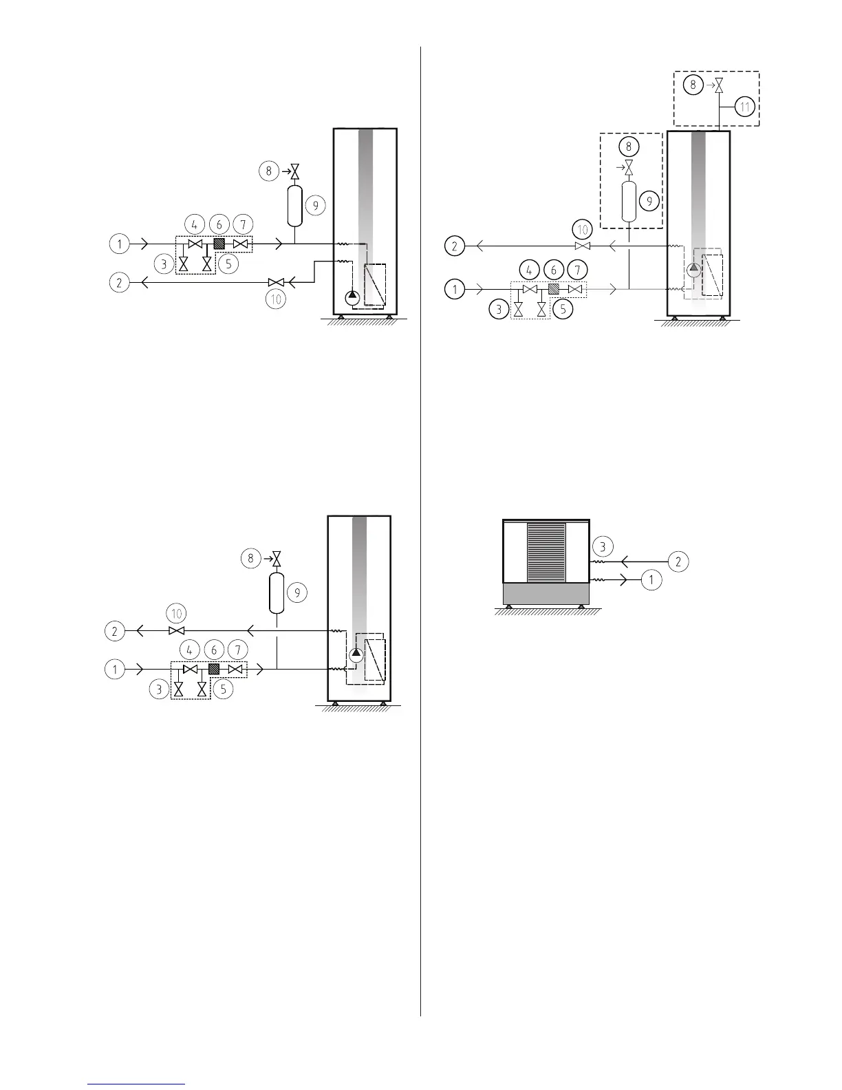
8.5 Connection diagram
The position lists show the components and parts included in the
delivery in italics.
DHP-C:
General connection diagram brine pipes, DHP-C.Figure 65:
Position Name
1 Brine in
2 Brine out
3 Shut-off valve
4 Shut-off valve
5 Shut-off valve
6 Strainer
7 Shut-off valve
8 Safety valve (1.5 bar)
9 Bleed and expansion tank
10 Shut-off valve
DHP-H, DHP-L:
General connection diagram, brine pipes Figure 66:
DHP-H, DHP-L.
Position Name
1 Brine in
2 Brine out
3 Shut-off valve
4 Shut-off valve
5 Shut-off valve
6 Strainer
7 Shut-off valve
8 Safety valve (1.5 bar)
9 Bleed and expansion tank
10 Shut-off valve
DHP-A:
General connection diagram brine pipes, DHP-A.Figure 67:
Position Name
1 Brine in
2 Brine out
3 Shut-off valve
4 Shut-off valve
5 Shut-off valve
6 Strainer
7 Shut-off valve
8 Safety valve (1.5 bar)
9 Bleed and expansion tank
10 Shut-off valve
11 Pressure tank
Outdoor unit:
Connection diagram, DHP-A -AL outdoor unitFigure 68:
Position Name
1 Brine out
2 Brine in
3 Flexible hoses
If the outdoor unit is installed
higher than the heat pump the
expansion outlet must be used
together with a pressure tank.
If the outdoor unit is installed at the same
level or lower than the heat pump, the
accompanying plastic vessel can be used.
The upper part of the outdoor unit must
then not exceed the fluid level in the
vessel.