[6]
[5]
[3]
[2]
[4]
[1]
130BB669.10
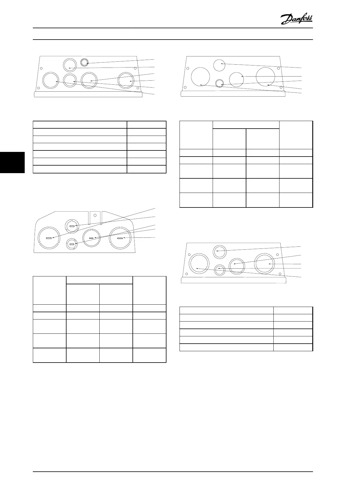
Illustration 6.29 B1 - IP55 Threaded Gland Holes
Hole Number and recommended use Nearest metric
1) Mains M32
2) Motor M32
3) Brake/Load Sharing M32
4) Control Cable M25
5) Control Cable M25
6) Control Cable
22.5 mm
1)
Table 6.11 Legend to Illustration 6.29
1)
Knock-out hole
[1]
[4]
[5]
[3]
[2]
130BB660.10
Illustration 6.30 B2 - IP21
Hole Number
and
recommended
use
Dimensions
1)
Nearest metric
UL [in] [mm]
1) Mains 1 1/4 44.2 M40
2) Motor 1 1/4 44.2 M40
3) Brake/Load
Sharing
1 34.7 M32
4) Control
Cable
3/4 28.4 M25
5) Control
Cable
1/2 22.5 M20
Table 6.12 Legend to Illustration 6.30
1)
Tolerance
±
0.2 mm
[4]
[3]
[5]
[2]
[1]
130BB668.10
Illustration 6.31 B2 - IP55
Hole Number
and
recommended
use
Dimensions
1)
Nearest metric
UL [in] [mm]
1) Mains 1 1/4 44.2 M40
2) Motor 1 1/4 44.2 M40
3) Brake/Load
Sharing
1 34.7 M32
4) Control
Cable
3/4 28.4 M25
5) Control
Cable
2)
1/2 22.5 M20
Table 6.13 Legend to Illustration 6.31
1)
Tolerance
±
0.2 mm
2)
Knock-out hole
[4]
[3]
[2]
[5]
[1]
130BB670.10
Illustration 6.32 B2 - IP55 Threaded Gland Holes
Hole Number and recommended use Nearest metric
1) Mains M40
2) Motor M40
3) Brake/Load Sharing M32
4) Control Cable M25
5) Control Cable M20
Table 6.14 Legend to Illustration 6.32
Electrical Installation
Design Guide
92 Danfoss A/S © Rev. 06/2014 All rights reserved. MG11BC02
66