DKRCC.PS.RI.A1.02 / 520H4358 - Air Handling Seq. user manual - V 2.2
Produced by Danfoss Electronics spa Graphic Department, 10-2009
18
Air Handling seq. - user manual
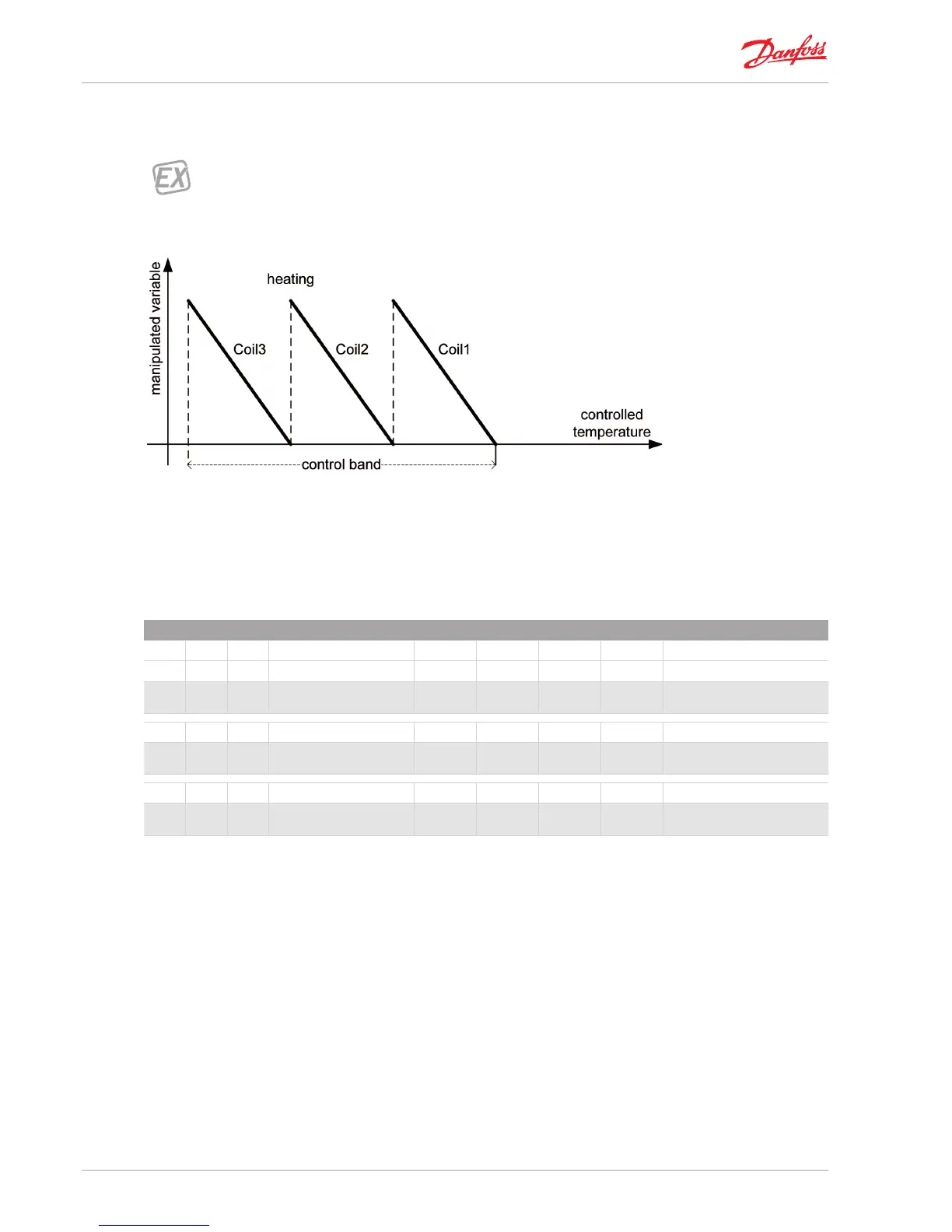
It is possible to congure more coils controlled with the same control sequence. In this case they share equally the
control band.
* Three coils for heating
controlled with Heat Sequence 1;
b10=b40=b70=HS1
Fig 6 _ [Coils control - example heat sequence]
4.2| Coil output management
The following parameters set the way coil output are managed according to the load demand calculated by the
associated temperature control sequences (see “6.2] Heat and cool control sequences”).
COIL OUTPUT MANAGEMENT
COI Coils Min Max Default U.M. Text value
CL1 Coil 1
b11 Actuator 1 type 1 4 VALVE VALVE;LIN STEP;VAR STEP;BIN
STEP
CL2 Coil 2
b41 Actuator 2 type 1 4 LIN STEP VALVE;LIN STEP;VAR STEP;BIN
STEP
CL3 Coil 3
b71 Actuator 3 type 1 4 LIN STEP VALVE;LIN STEP;VAR STEP;BIN
STEP
Tab 10_ [Coils control -Coil output management]
Through b11, b41, b71 you can dene the actuator type for each coil, whether it is a water coil controlled trough a
valve or it is a step controlled coil (e.g. electric resistances). In this case there are 3 possible way of control: linear step
switch, variable step switch binary step switch.