Air Handling seq.- user manual
DKRCC.PS.RI.A1.02 / 520H4358 - Air Handling Seq. user manual - V 2.2
Produced by Danfoss Electronics spa Graphic Department, 10-2009
37
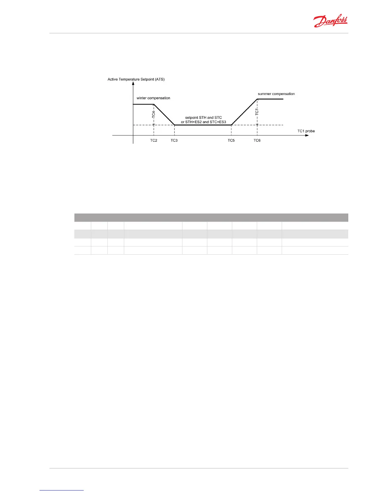
6.4.2| Temperature compensation
The setpoint can be compensated according to the value of a probe dened with TC1 parameter. If TC1=NO,
compensation is not enabled.
The way ATS is related to the TC1 probe values is described in the following gure.
Fig 25_ [Temperature control sequences - Temperature compensation]
Note that the diagram corresponds to positive values of TC4, TC7 and TC2 < TC3 < TC5 < TC6.
Typically the probe used for compensation is the outside probe “OUT – Outside Temp” (TC1=OUT) and then we can
talk about summer and winter compensation.
6.5| Local setpoint
LOCAL SETPOINT
SET Setpoint Min Max Default U.M. Text value
LST Local Setpoint
LS1 Local set1 -15,0 90,0 21,0 °C
LS2 Local set2 -15,0 90,0 90,0 °C
Tab 27_ [Temperature control sequences -Local setpoint]
Is possible to dene two “local” setpoint LS1 and LS2 which are not aected by economy mode and compensation
and are not accessible from the user interface in a shorten way.
Through parameters D02, D03, H12, H22, C12, they can be assigned to the specic sequence, (see “6] Temperature
control sequences”).