Air Handling seq.- user manual
DKRCC.PS.RI.A1.02 / 520H4358 - Air Handling Seq. user manual - V 2.2
Produced by Danfoss Electronics spa Graphic Department, 10-2009
7
LED DISPLAY
GEN General Min Max Default U.M. Text value
dSP Out Delay
dSA Display A value 1 17 RET ;NO;StH;StC;SUP;REt;OUt;tH1;tH2
;tC1;tC2;bAR;SHU;RHU;OHU;THU
;CO2;VOC
dUA Unit of measure A 1 4 °C ;NO;°C ;RH%;bAR
dSb Display B value 1 17 StH ;NO;StH;StC;SUP;REt;OUt;tH1;tH2
;tC1;tC2;bAR;SHU;RHU;OHU;THU
;CO2;VOC
dUb Unit of measure B 1 4 °C ;NO;°C ;RH%;bAR
Tab 2 _ [User interface -LED display]
Using dSA and dSB, you can choose which setpoint and probe reading values are to be shown on displays A and B
respectively.
dUA and dUb establishes the unit of measure used on the display A and B . The choices are: none, °C, RH%, bar.
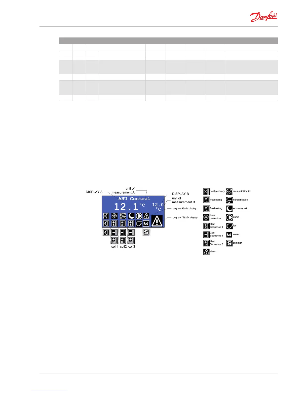
The meaning of the icons is indicated in the gure.
The icon associated with a given function follows the trend in activation/deactivation for that function.
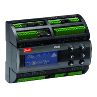
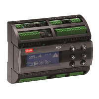
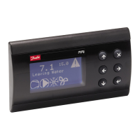
2.3.2| LCD Display
The rst screen displays:
the measurement detected by the two analog inputs (see “display
A” and “display B” for the version with LED display);
the symbols of the main active functions (see gure).
Fig 2 _ [User interface - LCD display]
»
»