20.4 Mounting Base
The compressor must be mounted on a rigid surface of sufficient structural integrity to support the weight of the
compressor and valves. Refer to the following figures and table for further details.
l Figure 16-10 TTH/TGH Center of Gravity Capacitor Side View
l Figure 1-9 Center of Gravity Top View (Excluding TTH/TGH Compressors
l Figure 16-10 TTH/TGH Center of Gravity Capacitor Side View
l Figure 1-11 TTH/TGH Center of Gravity Top View
l Table 1-2 Center of Gravity X-Y Coordinates
A mounting kit is available to isolate the compressor from the supporting structure and to minimize vibration from
other rotating equipment. The compressor mounting rails should be level ± 3/16” (5 mm) in the lateral and
longitudinal planes.
NOTE
If isolation pads are used at the four mounting base points, the overall height of the compressor will change. Be sure to measure
accordingly based on the insulator used.
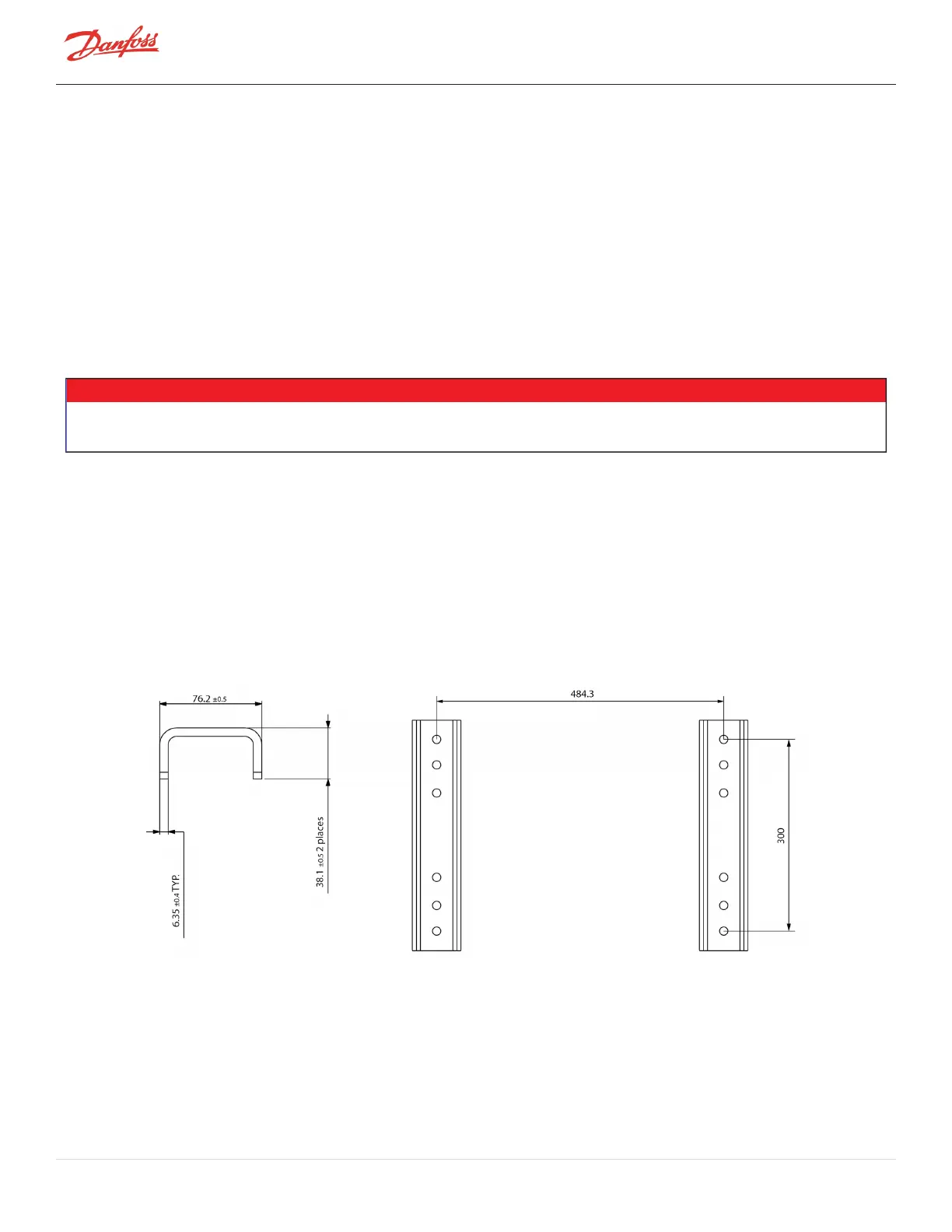
1. If isolation pads are used, install four pads in accordance with the footprint dimensions given in Figure
20-2 Mounting Base (TTS/TGS/TTH/TGH) Series.
2. Mount the compressor onto the isolation pads. Ensure the compressor mounting rails are properly
isolated from the base frame once the attaching hardware is secured; for example, the screw should
not extend from the compressor mounting rails to the base frame Figure 20-3 Incorrect Compressor
Mounting Pad Installation and Figure 20-4 Correct Compressor Mounting Pad Installation.
3. Check that the compressor mounting rails are level ± 5 mm (3/16”) in the lateral and longitudinal
planes.
Figure 20-2 Mounting Base (TTS/TGS/TTH/TGH) Series
Page 116 of 136 - M-AP-001-EN Rev. S 9/8/2021

 Loading...


