Chapter 3.0 Functional Description
Compressor operation begins with a call for cooling from a chiller controller. The compressor controller then begins
compressor ramp-up.
3.1 Main Fluid Path
The following paragraphs describe the flow of refrigerant from the intake to the discharge port of the compressor
(refer to Figure 3-1 Compressor Fluid Path TGS230/TTS300 and Figure 3-2 Compressor Fluid Path (TGS310, TTS350,
TGS390, TGS490, TTS400, TGS520, and TTS700).
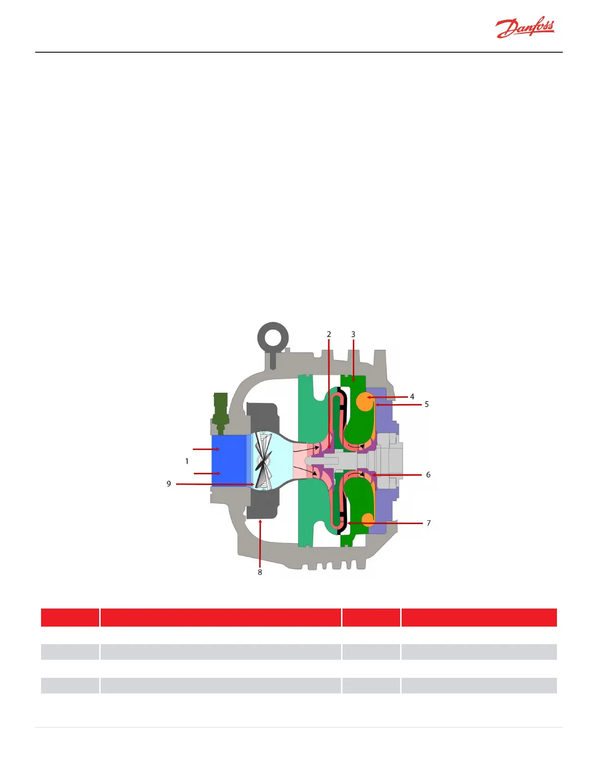
The refrigerant enters the suction side of the compressor as a low-pressure, low-temperature, superheated gas. The
refrigerant gas passes through a set of adjustable Inlet Guide Vanes (IGVs) that are used to control the compressor
capacity at low-load conditions. The first compression element the gas encounters is the first-stage impeller. The
centrifugal force produced by the rotating impeller results in an increase in both gas velocity and pressure. The
high-velocity gas discharging from the impeller is directed to the second-stage impeller through de-swirl vanes. The
gas is further compressed by the second-stage impeller and then discharged through a volute via a diffuser (a volute
is a curved funnel increasing in area to the discharge port; as the area of the cross-section increases, the volute
reduces the speed of the gas and increases its pressure). From there, the high-pressure/high-temperature gas exits
the compressor at the discharge port.
Figure 3-1 Compressor Fluid Path TGS230/TTS300
Table 3-1 Compressor Fluid Path TGS230/TTS300
No. Description No. Description
1 Low-Pressure/Low Temperature Gas 6 Second-Stage Impeller
2 First-Stage Impeller 7 Vaned Diffuser
3 Volute Assembly 8 IGV
4 Discharge Port 9 Vanes
5 High-Pressure/High Temperature Gas
M-AP-001-EN Rev. S-9/8/2021 Page 25 of 136

 Loading...


