3.4 Compressor Control Overview
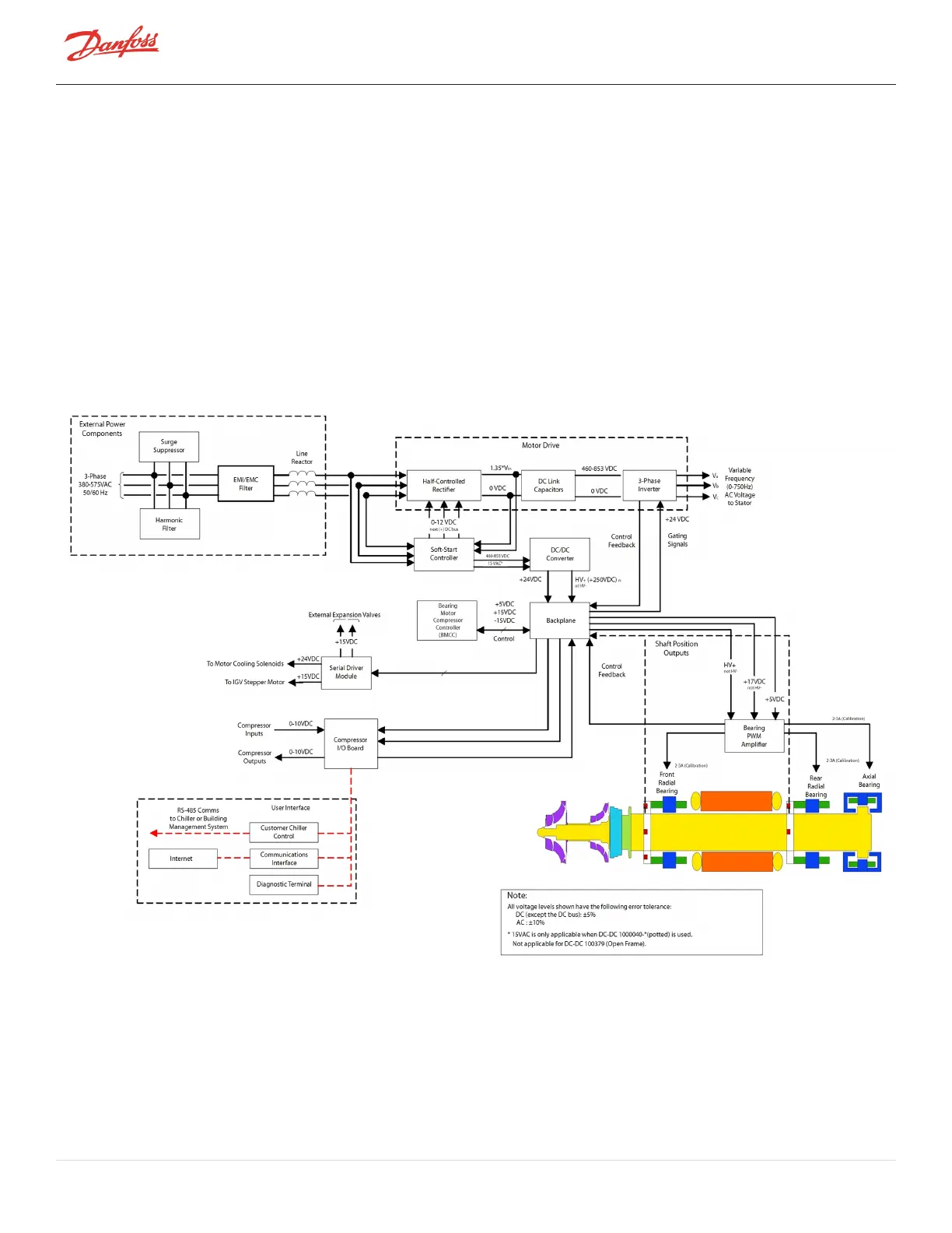
Refer to Figure 3-6 Compressor Control System Functional Block Diagram which shows a functional block diagram of
the compressor control and monitoring system. Refer to Figure 3-8 Magnetic Bearing Control System which displays
the component locations. The major components include:
l Motor Drive
l Soft-Start Board
l BMCC
l Bearing PWM Amplifier
l Backplane
l Serial Driver
l HV DC-DC Converter
Figure 3-6 Compressor Control System Functional Block Diagram
3.4.1 Motor Drive System
Normally, AC power to the compressor remains on even when the compressor is in the idle state. The compressor
motor requires a variable-frequency three-phase source for variable-speed operation. The AC line voltage is
converted into a DC voltage by SCRs. DC capacitors at the SCR output serve as energy storage and filter out the
Page 30 of 136 - M-AP-001-EN Rev. S 9/8/2021

 Loading...


