Table 3-6 Backplane LEDs
LED Function
+5V, +15V, +17HV, +24V LEDs are lighted when DC power is available.
Cool-H, Cool-L LEDs are lighted when their respective coil is energized.
Run LED is lighted when the shaft is spinning.
Alarm LED is green when in normal status, red when in alarm status.
D13, D14, D15, D16 LEDs indicate IGV status and flash when IGV is moving.
3.4.13 High-Voltage DC-DC Converter
DC-DC converters supply and electrically isolate the high and low DC voltages that are required by the control
circuits. The HV DC-DC Converter delivers 24VDC and 250VDC from an input of 460-900VDC. The 24VDC and
250VDC are used to power the Backplane and magnetic bearing PWM Amplifier, respectively.
3.5 Magnetic Bearing System
3.5.1 Overview
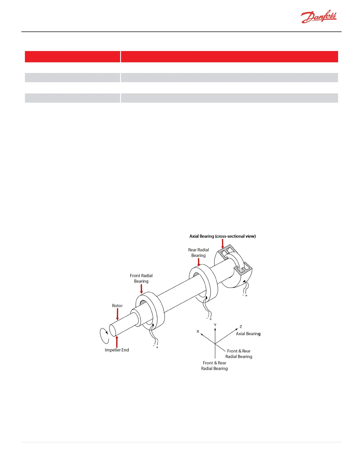
A rotating shaft, under changing load conditions, will experience forces in both radial and axial directions. In order
to compensate for these forces, a five-axis bearing system is used, incorporating two radial bearings of two axes
each, and one thrust (axial) bearing. Refer to Figure 3-7 Magnetic Bearing Configuration
Figure 3-7 Magnetic Bearing Configuration
3.5.2 Bearing Control System
The Bearing Control System uses rotor position feedback to close the loop and maintain the rotor in the correct
running position (refer to Figure 3-8 Magnetic Bearing Control System). The Bearing Controller issues position
commands to the Bearing PWM Amplifier. The position commands consist of five channels with each channel
M-AP-001-EN Rev. S-9/8/2021 Page 33 of 136

 Loading...


