Appendix B
B.1 EMI/EMC Filter Installation Instructions
1. Mount the filter on the floor or on a wall in a vertical position.
2. Ensure there is a minimum of 60mm (2 3/8”) of space for the cooling slots.
B.1.1 Line Side Connection
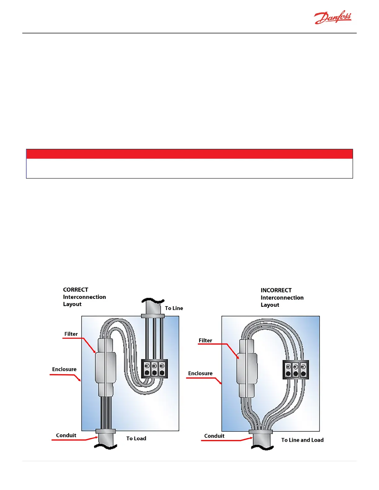
Input and output filter leads should be separated by a maximum practical distance within the enclosure and should
be routed separately in interconnecting conduits when used (refer to Figure B-1 Interconnection Layout).
1. Insert the line wires into the terminals labeled "L1," "L2," and "L3" on the "Line" side of the filter.
Tighten the terminal screws.
2. Attach the ground lug to the main ground bus and tighten the nut (refer to Figure B-2 Grounding
Diagram).
NOTE
A short, heavy, stranded conductor from the filter chassis to the main ground bus is recommended for top performance. A battery braid,
litz wire, or flexible welding cable with many fine strands is recommended for best grounding performance.
B.1.2 Load Side Connection
1. Insert the load wires (instead of the line side of the line reactor) into the terminals labeled "L1," "L2,"
and "L3" on the "Load" side of the filter. Tighten the terminal screws.
2. Attach the ground lug to the main ground bus and tighten the nut.
B.1.3 Harmonic Filter
1. If a harmonic filter is to be installed, follow the manufacturers instructions.
2. Connection of a harmonic filter should be made on the Load side of the Line Reactor (refer to Figure
20-9 Typical Electrical Connections).
Figure B-1 Interconnection Layout
M-AP-001-EN Rev. S-9/8/2021 Page 127 of 136

 Loading...


