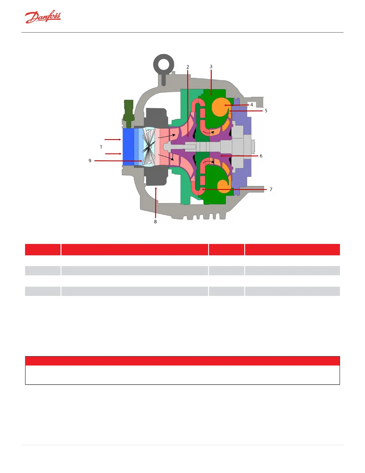
Figure 3-2 Compressor Fluid Path (TGS310, TTS350, TGS390, TGS490, TTS400, TGS520, and TTS700)
Table 3-2 Compressor Fluid Path (TGS310, TTS350, TGS390, TGS490, TTS400, TGS520, and TTS700)
No. Description No. Description
1 Low-Pressure/Low Temperature Gas 6 Second-Stage Impeller
2 First-Stage Impeller 7 Vaneless Diffuser
3 Volute Assembly 8 IGV
4 Discharge Port 9 Vanes
5 High-Pressure/High Temperature Gas
3.2 Motor Cooling
Liquid refrigerant is channeled at full condenser pressure from the main liquid line to the compressor to cool the
electronic, mechanical, and electromechanical components (refer to Figure 3-3 Compressor Cooling Circuit (TGS230
/ TTS300) and Figure 3-4 Compressor Cooling Circuit (TTS300 Split-Cooling, TGS310, TTS350, TGS390, TGS490,
TTS400, TTS700, and TGS520).
• • • CAUTION • • •
A minimum operating pressure ratio of 1.5 is required to maintain adequate cooling of the compressor, unless the system is fitted with an
appropriately selected liquid pump cooling pump.
The sub-cooled refrigerant enters the compressor through two solenoid valves and associated fixed orifices located
behind the service access cover. The orifices cause the refrigerant to expand, thereby lowering its temperature. Both
valves open in response to the temperature sensed in the motor and inverter.
Page 26 of 136 - M-AP-001-EN Rev. S 9/8/2021

 Loading...


