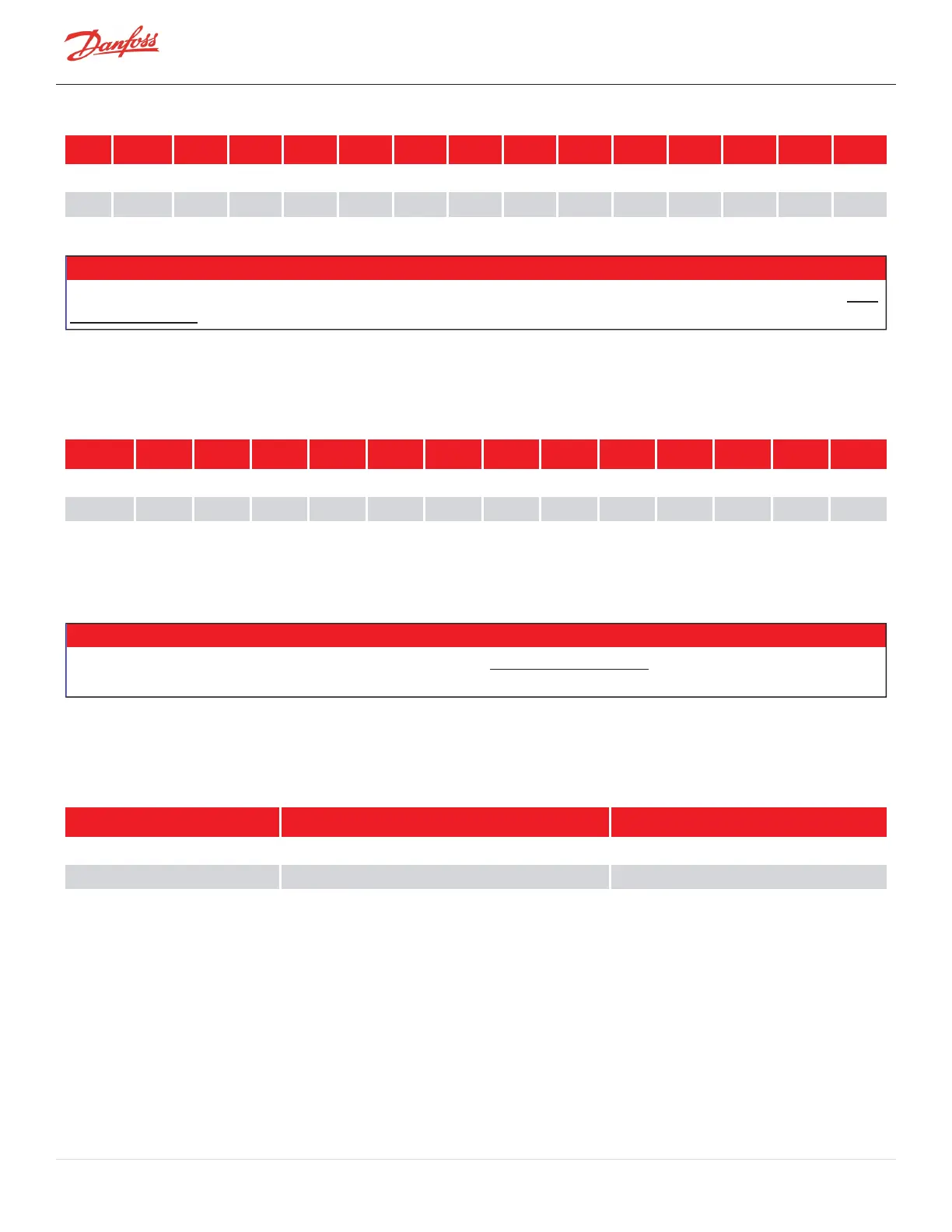
Table 5-2 Discharge Temperature Fault Settings
Unit Compressor TGS230ST TGS230MT TGS310 TGS490 TGS390 TGS520 TGH285 TTS300ST TTS300MT TTS350 TTS400 TTS700 TTH375
°F Fault 212 194 203 203 194 194 212 121 194 203 194 194 212
°C Fault 100 90 95 95 90 90 100 100 90 95 90 90 100
NOTE
While the values here are represented in Gauge Pressure, the values in the registers will be defined in Absolute Pressure. Refer to the OEM
Programming Manual to identify the specific registers associated with the Discharge Pressure Alarm and Discharge Pressure Fault Limits.
The compressor will also adjust its operation if the pressure ratio exceeds the alarm limit. The Pressure Ratio alarm
limit is defined in Table 5-3 Maximum Pressure Ratio Limits.
Table 5-3 Maximum Pressure Ratio Limits
TGS230ST* TGS230MT* TGS310 TGS490 TGS390 TGS520 TGH285 TTS300ST* TTS300MT* TTS350 TTS400 TTS700 TTH375
Alarm 4 4 5.2 5.2 3.5 3.5 6.3 4 4 5.2 3.5 3.5 6.3
Fault 5.2 5.2 5.5 5.5 4 4 6.5 5.2 5.2 5.5 4 4 6.5
*The TGS230/TTS300 compressor allows for adjustment of this setting. Compressors which are placed in Air-Cooled
applications can have this value increased up to 4.8.
NOTE
Pressure ratio must be calculated using absolute pressures. Refer to the OEM Programming Manual to identify the specific register
associated with the Pressure Ratio Alarm Limit.
Beyond these control limits, the Maximum Design High-Side Pressure for the compressor is shown in Table 5-4
Maximum Allowable Pressure [PS].
Table 5-4 Maximum Allowable Pressure [PS]
Unit All TTS &TGS Compressors TTH/TGHCompressors
kPag 2070 2303
psig 300 334
5.4 Suction Pressure Limits
The Suction Pressure Alarm and Fault Limits are displayed in the Table 5-5 Suction Pressure Alarm and Fault
Settings.
Page 42 of 136 - M-AP-001-EN Rev. S 9/8/2021

 Loading...


