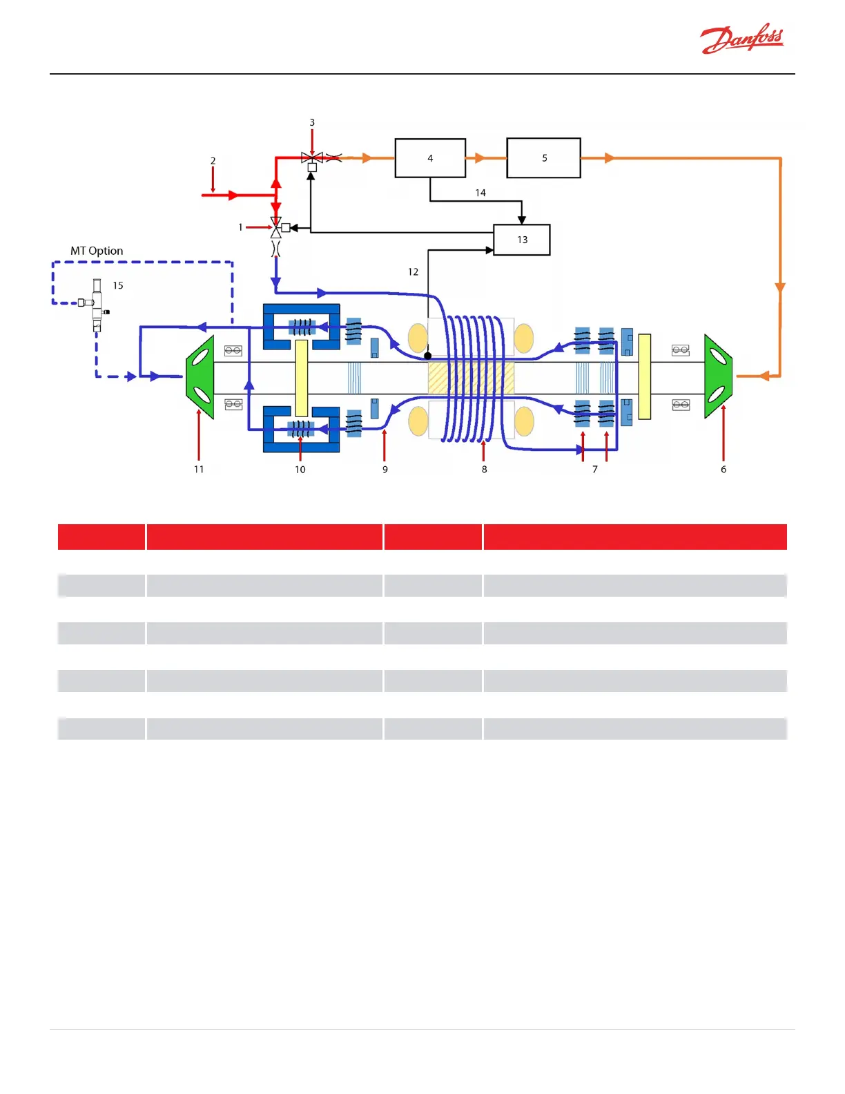
Figure 3-5 Highlift Cooling Circuit Flow Diagram (TGH285/TTH375)
Table 3-5 Highlift Cooling Circuit Flow Diagram (TGH285/TTH375)
No. Description No. Description
1 Solenoid M 9 Radial Bearing
2 Liquid Refrigerant Inlet 10 Axial Bearing
3 Solenoid E 11 Impeller - 1
st
Stage
4 Inverter 12 Motor Cavity Temp. Sensor
5 SCR 13 BMCC
6 Impeller - 2
nd
Stage 14 Inverter Temp Sensor
7 Radial Bearing 15 PRV (pressure regulating valve)
8 Stator/Rotor
3.3 Inlet Guide Vanes
The Inlet Guide Vane (IGV) assembly is a variable-angle guiding device that is used for capacity control. The IGV
assembly consists of movable vanes and a motor. The vane opening is determined by the BMCC and controlled by
the Serial Driver. The IGV position can vary between 0-110% where 0% is fully closed and 110% is fully open with the
vanes at a 90° angle.
M-AP-001-EN Rev. S-9/8/2021 Page 29 of 136

 Loading...


