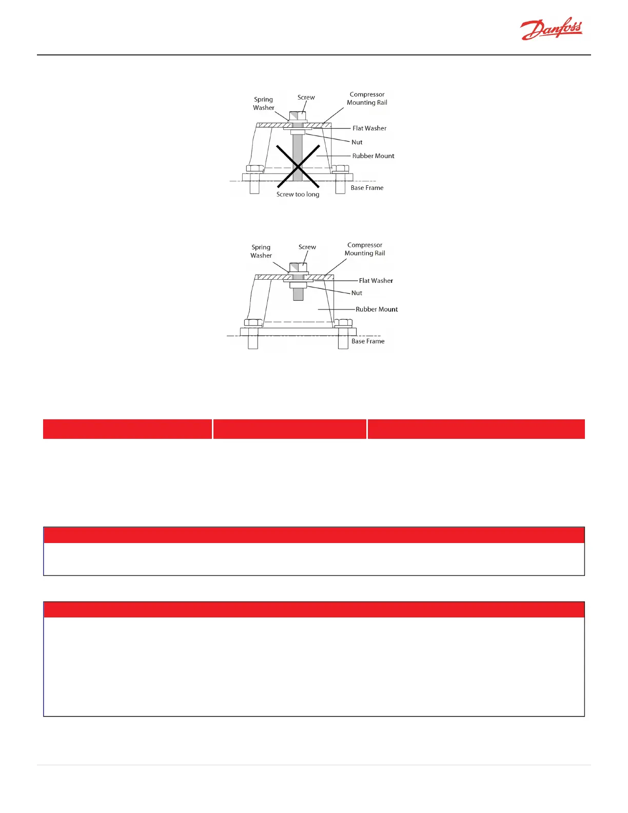
Figure 20-3 Incorrect Compressor Mounting Pad Installation
Figure 20-4 Correct Compressor Mounting Pad Installation
In the event the mounting base is not used and the compressor is secured directly to the chiller, refer to the fastener
specifications in Table 20-1 Mounting Base Screw Hole Specifications.
Table 20-1 Mounting Base Screw Hole Specifications
Fastener Thread Spec Thread Depth (mm) Recommended Torque (Nm)
M12 24 22
20.5 Piping Connections
• • • CAUTION • • •
Install new O-rings when attaching flanges to the compressor. The OEM must make sure all sealing materials and equipment on the unit
are compatible with the appropriate refrigerant.
• • • DANGER • • •
The motor-cooling line should be channeled from the liquid line ( Figure 20-5 Motor-Cooling Connection and Access Port
The motor-cooling line requires the installation of a service valve (not included) to enable refrigerant isolation during compressor
servicing.
Compressors are pressurized with nitrogen to (15 psi). Pressure should be relieved through the Schrader valve, located next to the motor
cooling connection, prior to removing the blanking plates. Isolation and recovery of the refrigerant must be performed by a qualified
technician. Always wear proper safety equipment when handling refrigerants ( Figure 20-5 Motor-Cooling Connection and Access Port).
M-AP-001-EN Rev. S-9/8/2021 Page 117 of 136

 Loading...


