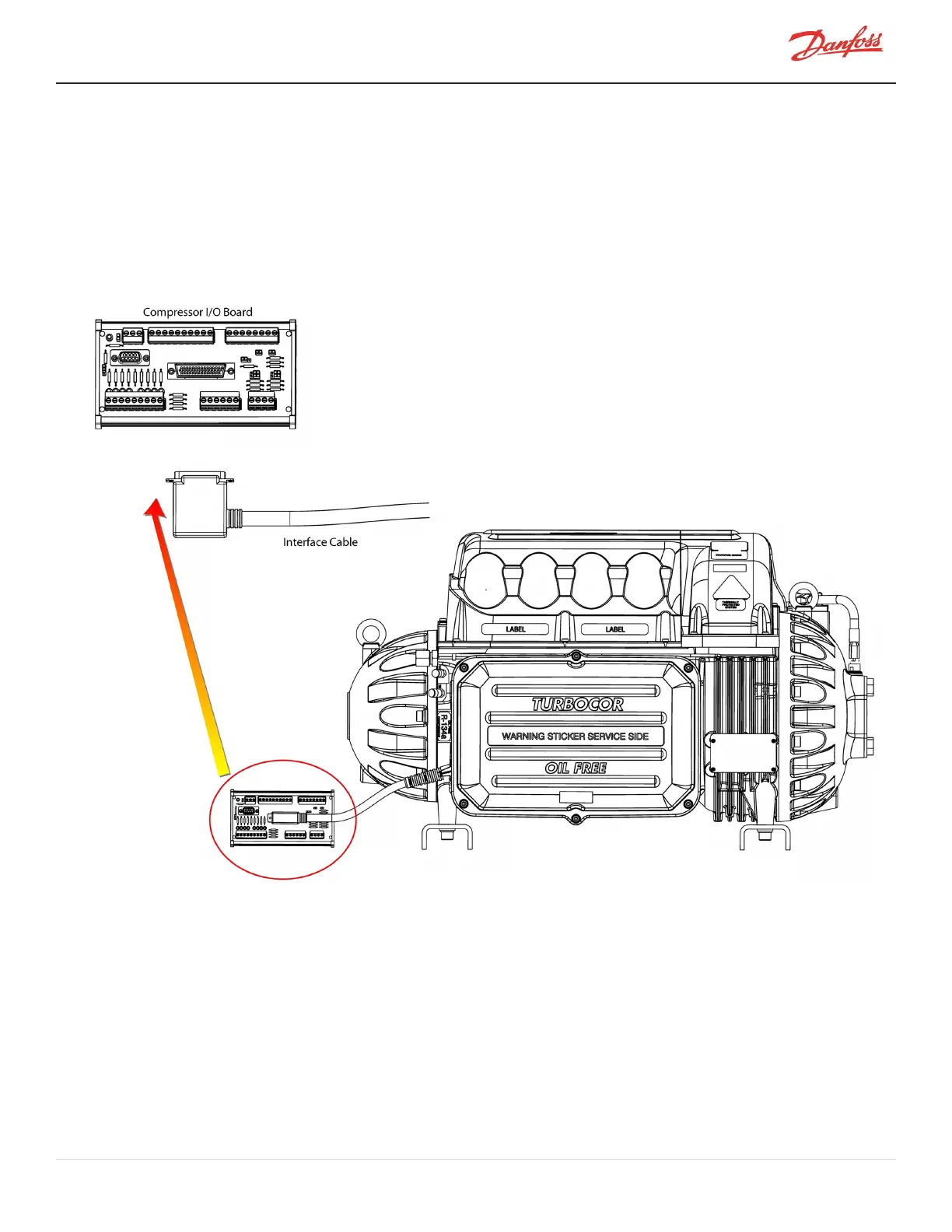
The interface cable connects the compressor to the compressor I/O board. To connect the cable:
1. Plug the cable connector into connector J6 on the compressor I/O board.
n For RS-485 communication, the total length of the interface cable and control wiring can be
extended up to 100 meters (328 feet) (refer to Figure 1-1 Typical Control Wiring Figure 4-3
I/OWiring Specifications. If the compressor is going to be monitored over an RS-232 line, the
total cable length between the compressor and the PC should not exceed 15 meters (50 feet).
Refer to Figure Interface Cable.
Figure 20-6 Compressor I/O Board Connections
20.6.2 Circuit Grounding
Improper grounding or voltage in circuits connected to the compressor I/O board can lead to component failures. In
particular, the interlock and analog output circuits are sensitive to improperly connected external circuits (refer to
Figure 20-7 Interlock and Motor Speed Connections
Prior to connecting the control wiring to the compressor I/O board, check for improper grounding. Improper
grounding can be identified by measuring the voltage between the customer’s negative terminals and the ground
(J1 COM or Modbus shield) terminal on the compressor I/O board (refer to Figure 20-7 Interlock and Motor Speed
Connections If the measured voltage is not zero (0), determine the source of the voltage. The most likely cause of
M-AP-001-EN Rev. S-9/8/2021 Page 119 of 136

 Loading...


