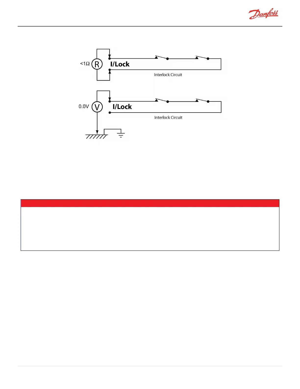
Figure 20-8 Interlock Circuit Tests
Measure the voltage between each customer interlock terminal and the frame ground while the interlock contacts
are open and closed. In either contact state, if the measured voltage is not zero (0), verify the source of the voltage.
Do not connect the interlock terminals until the voltage source is removed (refer to Figure 20-9 Typical Electrical
Connections).
20.7 Power Wiring
This section describes the connection of the power wiring to the compressor.
NOTE
l The AC input cable should be CSA, UL, or CE approved, 3-wire with a common shield and single ground. It is recommended
that the cable be double-jacketed; for example, a teck cable type. The cable must be rated for 90° C (194° F) minimum with a
maximum current rating corresponding to the LRA value on the compressor nameplate.
l Keep power cables and control interface cables in separate conduits. Use metal cable glands for shielded cables to ensure
good grounding.
l If you are installing a line reactor or EMI or harmonic filter in the mains input circuit, refer to Figure 20-9 Typical Electrical
Connections for the proper placement within the input power wiring.
Figure 20-9 Typical Electrical Connectionsshows a typical schematic for the compressor’s electrical connections.
M-AP-001-EN Rev. S-9/8/2021 Page 121 of 136

 Loading...


