Appendix A
A.1 Line Reactor Installation Instructions
These instructions apply to the installation of the line reactor kit in a main supply panel. Refer to the Spare Parts
Selection Guide for product specifications.
A.1.1 AC Line Cable Connection (From External Disconnect)
NOTE
The customer is responsible for supplying the mounting hardware for the line reactor.
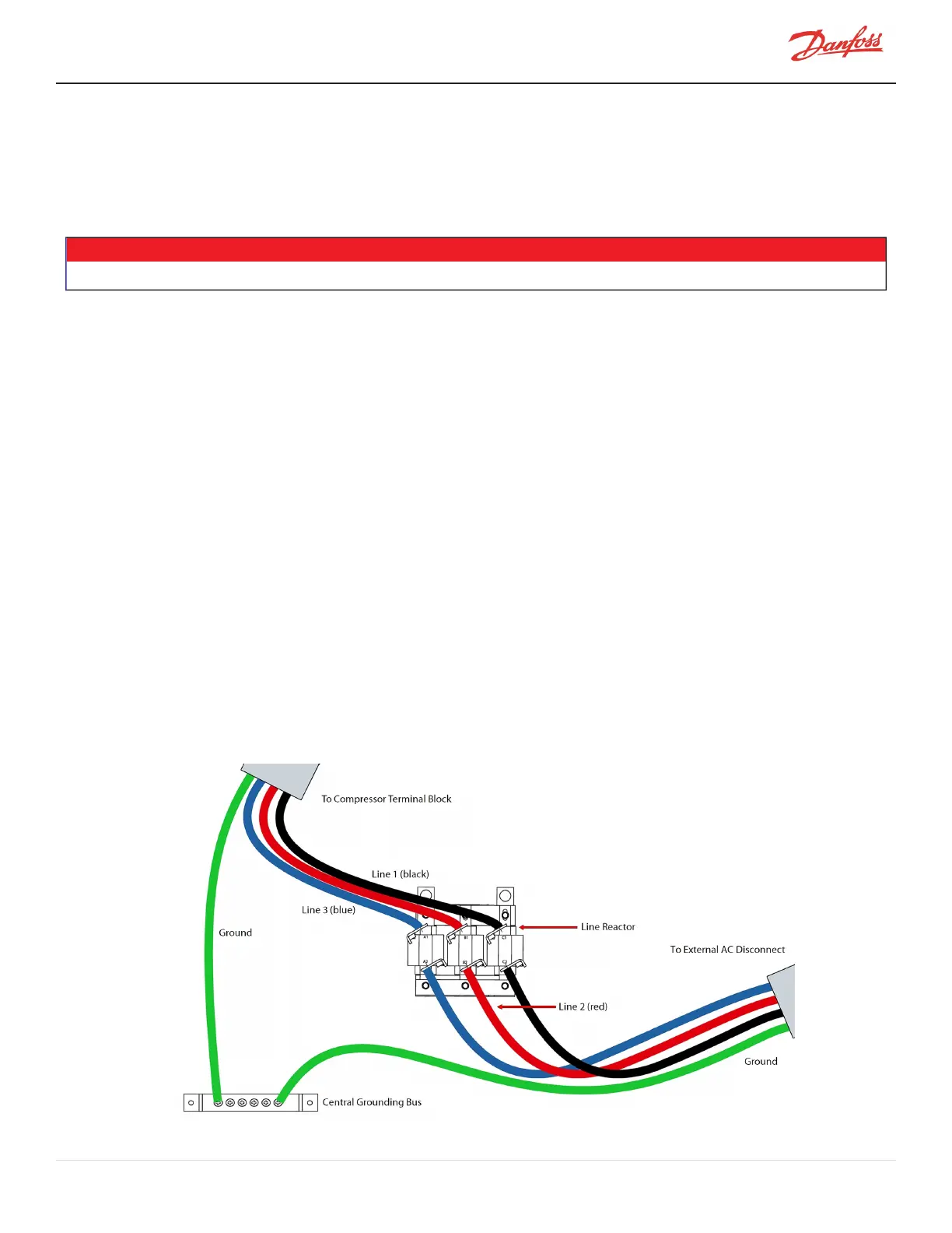
1. Figure A-1 Line Reactor Connections shows a schematic of the main input circuit and connections to
the line reactor. Use this schematic as a guide for choosing the location of the line reactor.
2. Feed the AC line cable through the opening in the side of the main supply panel.
3. Attach the AC line wires to the line reactor terminals as shown in Figure A-1 Line Reactor Connections.
4. Attach the ground cable to the mounting block on the panel wall. Ensure there is good
electrical/mechanical contact between the ground cable and the panel wall.
5. Secure the AC line cable to the main supply panel using approved methods (e.g., cable gland).
A.1.2 AC Line Cable Connection (to Compressor Terminal)
1. Feed the AC line cable through the opening in the side of the main supply panel.
2. Attach the AC line wires to the line reactor output terminals as shown in Figure 1-1 Line Reactor
Connections.
3. If a harmonic filter is being installed, attach its AC line wires to the line reactor output terminals.
4. Attach the ground wire to the mounting block on the panel wall. Ensure there is good
electrical/mechanical contact between the ground wire and the panel wall.
5. Secure the AC line cable to the main supply panel using approved methods (i.e., cable gland).
6. Refer to Section 20.7 Power Wiring for instructions on completing the AC input connection to the
compressor.
Figure A-1 Line Reactor Connections
M-AP-001-EN Rev. S-9/8/2021 Page 125 of 136

 Loading...


