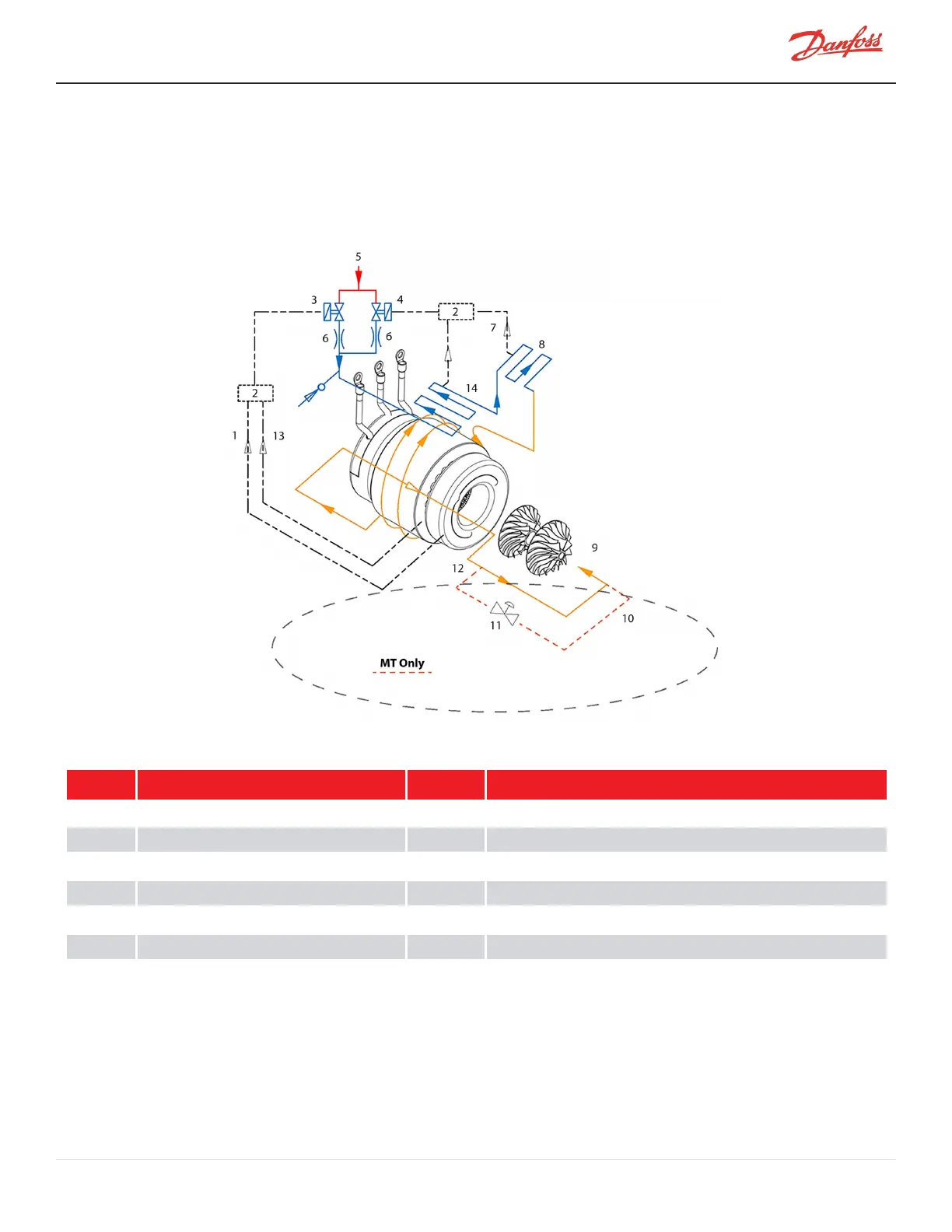
From the outlet of the orifices, the refrigerant is directed to the heatsink plate of the inverter and to the underside of
the SCR heatsink. The refrigerant also passes through grooves surrounding the motor stator. As the refrigerant flows
through the grooves, it vaporizes into a gas. At the coil outlet, the refrigerant gas is channeled back to the suction
inlet via the motor cavity, thereby cooling the rotor. All models with the exception of the TTS300 and TGS230 use a
split-cooling method where the motor and electronics portions are cooled separately by refrigerant liquid.
Figure 3-3 Compressor Cooling Circuit (TGS230 / TTS300)
Table 3-3 Compressor Cooling Circuit (TGS230 / TTS300)
No. Description No. Description
1 From Motor Winding Temp Sensor 8 SCR
2 BMCC 9 Motor/Rotor Cooling Gas and Leakage
3 Solenoid M 10 Cooling path re-enters at the suction line of the chiller
4 Solenoid E 11 Pressure Regulating Valve
5 Liquid Refrigerant Inlet 12 Cooling path redirects outside of the compressor
6 Orifice 13 From Motor Cavity Temp Sensor
7 From Inverter Temp Sensor 14 Inverter
M-AP-001-EN Rev. S-9/8/2021 Page 27 of 136

 Loading...


