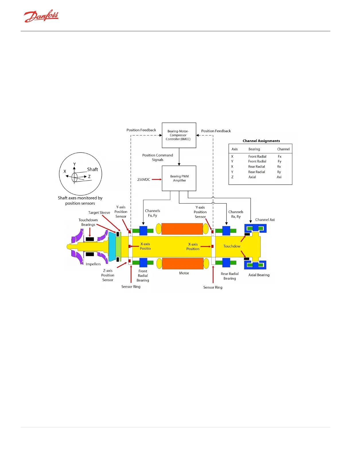
allocated to one of the five bearing actuator coils (one coil for each axis). The amplifier uses Inverter technology to
convert the low-voltage position commands to the 250VDC PWM signals that are applied to each bearing actuator
coil.
Rotor position sensors are located on rings attached to the front and rear radial bearing assemblies. The front sensor
ring contains sensors that read the rotor position along the X, Y, and Z axes. The rotor position along the Z (or axial)
axis is read by measuring the distance between the sensor and a target sleeve mounted on the rotor. The rear
sensor ring contains sensors that read the position along the X and Y axes. Information from the position sensors is
continuously fed back to the bearing controller.
Figure 3-8 Magnetic Bearing Control System
Page 34 of 136 - M-AP-001-EN Rev. S 9/8/2021

 Loading...


