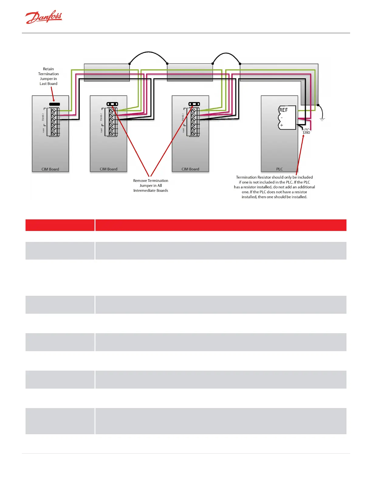
Figure 4-2 Modbus Grounding Diagram
Table 4-1 Control Wiring Details
I/O Description
COM (shield) Shield for RS-485 communication.
Modbus RS-485
NetB/NetA
Modbus over RS-485 communication port.
Stepper Motor 1 Phase
1A, 1B, 2A, 2B, and
Stepper Motor 2 Phase
1A, 1B, 2A, 2B
Optional output connections for controlling the main electronic expansion valve (evaporator) or auxiliary
electronic expansion valve (economizer or load balancing valve). 200ma Maximum output on each driver.
Valve frequency will effect operational characteristics.
Level Sensor +15V
(Evaporator)
Power supply for level sensor #1.
Sensor Signal
(Evaporator)
Input from a level sensor to control the main expansion valve (evaporator).
Level Sensor +15V
(Economizer)
Power supply for level sensor #2.
Sensor Signal
(Economizer)
Input from a level sensor to control the auxiliary expansion valve (economizer).
Demand 0 - 10V Analog input from customer-supplied controller to drive the compressor, i.e., 0 - max. kW input with a
deadband of 2VDC for the respective compressor model. Only available in 3.1.4; removed in 4.x forward.
Interlock Connects to a set of external normally closed contacts that typically open in the event of loss of chilled
water or air flow. Typically a 1.5VDC Output signal. NOTE: This is not a safety certified interlock.
Status An internal normally open contact that is closed during normal operation and opens in the event of a
compressor fault. With the circuit open, the compressor will not restart until the demand signal has been
reset to 0 (via chiller/unit controller). Circuit rated at 1A @ 30VDC/24VAC or .03A @ 120VAC.
Liquid Temperature Optional input for monitoring temperature. The temperature sensor must be an NTC type 10K @ 25°C
Page 36 of 136 - M-AP-001-EN Rev. S 9/8/2021

 Loading...


