Chapter 5 Function code VFD500 high performance vector control frequency inverter user manual
PLC step 9-12
ACCEL/DECEL
time selector
Unit’digit: ACCEL/DECEL time 9#
ten’digit: ACCEL/DECEL time 10#
Hundred’digit: ACCEL/DECEL time 11#
Thousand’digit: ACCEL/DECEL time 12#
0- ACCEL/DECEL time 1#
1- ACCEL/DECEL time 2#
2- ACCEL/DECEL time 3#
3- ACCEL/DECEL time 4
PLC step 13-16
ACCEL/DECEL
time selector
Unit’s Digit: ACCEL/DECEL time 13#
Ten’Digit: ACCEL/DECEL time 14#
Hundred’digit: ACCEL/DECEL time 15#
Thousand’s digit: ACCEL/DECEL tim 16#
0- ACCEL/DECEL time 1#
1- ACCEL/DECEL time 2#
2- ACCEL/DECEL time 3#
3- ACCEL/DECEL time 4
PLC stop
decelerating
time
0.01~60000s
Setting value decide by P03.16
P03.16 = 2, 0.00~600.00s;
P03.16 = 1, 0.0s~6000.0s;
P03.16 = 0, 0s~60000s
43 Group Programming delay-unit
It is used to view the current output status of
the delay unit.
Bit definition is used, Bit0~Bit3 respectively
indicate the output status of delay units 1~4,
0 means invalid, 1 means valid.
0000B~1111B
Bit0~Bit3 corresponds to delay units 1~4,
which are used to specify whether the
output of the delay unit is inverted.
Delay unit 1
input parameter
selection
00.00-98.99(function code index)
Delay unit 1
input bit
selection
Delay unit 1
rising edge
delay time
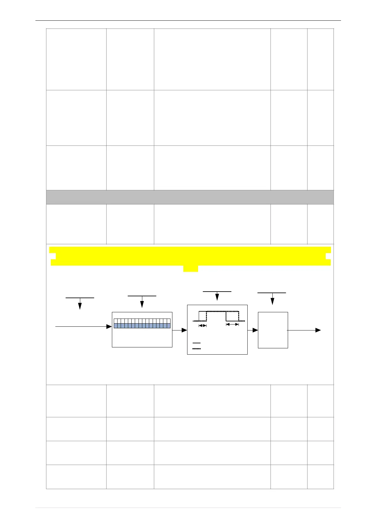
VFD500 inverter built-in 4 delay unit. The delay unit can collect the status of 0 ~ 15 bits of all parameters that can
be viewed in the function code table, and finally output the delay unit status after delay processing and logic
selection. Can be used for DI / DO, comparator / logic unit output delay and other functions, but also as a virtual
relay.
Delay unit 1 block diagram
The picture shows the delay unit 1 block diagram, delay unit 2 to 4 and so on. Delay unitsDelay can be used for
DI/DO delay processing also can be combined with comparator units and logic units for more complex
applications.
Input Ref
(P43.02 The value of the
selected function code)
Parameter bit selection
P43.03=x
Delay processing
P43.04, P43.05
0-not
reversed
1-reverse
Logical selection
No. 0 of P43.01
Delay unit 1
output
parameter
selection
P43.02
input
output
P43.04 P43.05
Take the xth (0~15) bit
of Ref
 Loading...

