Chapter3 product appearance and wiring VFD500 high performance vector control frequency inverter user manual
Table 3-21 Functional Description of VFD500 Jumper Switch
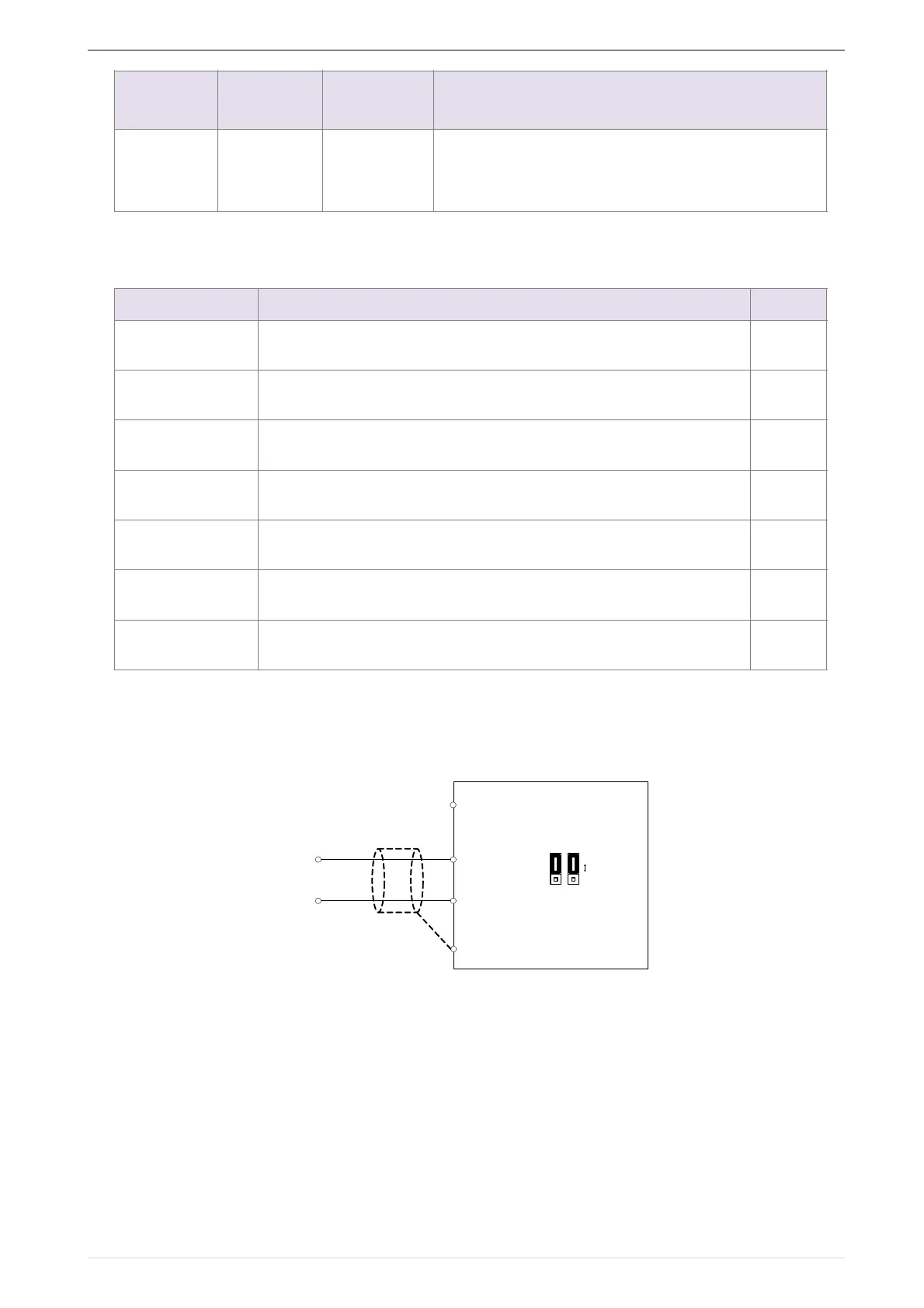
◆ Analog input terminal instructions
The AI1 and AI2 terminals can accept both analog voltage input and analog current input. They
can be switched by jumpers “AI1” and “AI2” on the IO board. The connection method and jumper
switch configuration are shown in the following figure:
!
Figure 3-22 Analog input terminal wiring diagram
The AO1 and AO2 terminals support the voltage output (0~10V) and the current output (0~20mA). They are
selected by jumpers “AO1” and “AO2” on the IO board. The connection method is as shown in the figure below:
485 Negative
differential
signal
1200/2400/4800/9600/19200/38400/57600/115200b
ps
Terminal function description
485 Termination resistor selection: ON has 100 ohm terminating
resistor, OFF is no terminating resistor
AI1 analog type selection: V is the voltage input (0 ~ 10V), I is the
current input (0 ~ 20mA)
AI2 analog type selection: V is the voltage input (0 ~ 10V), I is the
current input (0 ~ 20mA)
AO1 analog type selection: V is the voltage output (0 ~ 10V), I is
the current output (0 ~ 20mA)
AO2 analog type selection: V is the voltage output (0 ~ 10V), I is
the current output (0 ~ 20mA)
GND ground selection: ON is grounded through the safety
capacitor, OFF is not connected
COM ground selection: ON is grounded through the safety
capacitor, OFF is not connected
VFD500
+
-
1 -/0 1
Jumper
switch
Voltage input
Current input
-