Chapter 4 Operation and display VFD500 high performance vector control frequency inverter user manual
Chapter 4 Operation and display
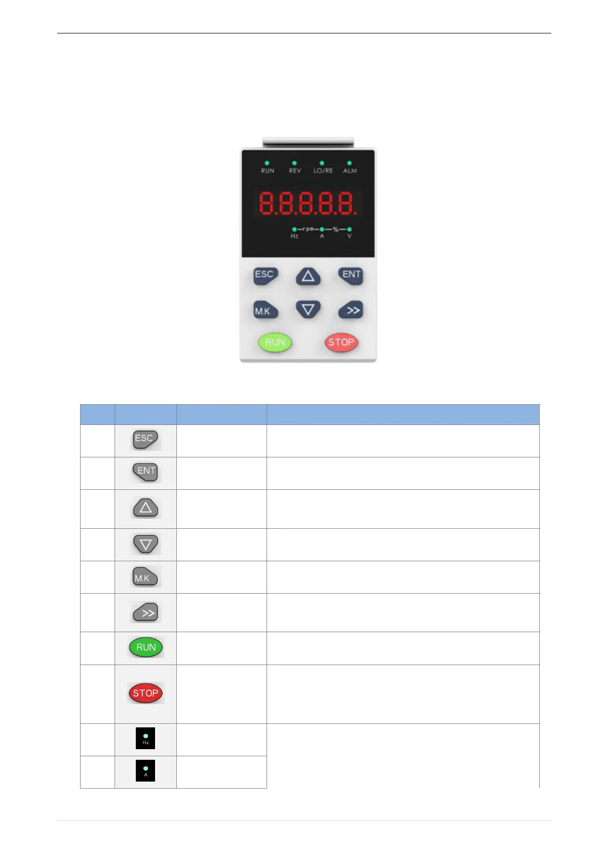
4.1 LED Instruction of operation and display
LED keyboard consists of 5 digital tubes, 7 lights, 8 keys and a potentiometer; can be used to set
the parameters, status monitoring and operation control, LED keyboard shape as shown in Figure 4-1:
!
Figure 4-1 Operating panel
Description of indicator
Table 4-1 The name and function of each part of the keyboard
•
Enter the menu interfaces level by level,
•
confirm the parameter setting and save to EEPROM
• The number indicated by the cursor increases by one.
• Next function code.
• Used to switch the left and right screens while in monitor mode
·The number indicated by the cursor minus one.
• The previous function code.
·
Perform function switchover according to the setting of
21.02
• Cursor shift.
• Monitor Status Displays the next monitor volume.
• Switch left and right screens.
Start the frequency inverter in the operation panel control
mode
• During operation, press to stop the operation (restricted by
parameter 21.03).
• In fault status, press this key to reset the fault.
·Indicate the digital display unit, all three lights off menas other
units
 Loading...

