EasyManuals Logo

Danfoss VFD500 Series User Manual

Danfoss VFD500 Series
137 pages
To Next Page IconTo Next Page
To Previous Page IconTo Previous Page
Page #35 background imageLoading...
Page #35 background image
VFD500 high performance vector control frequency inverter user manual Chapter3 Product appearance and wiring
!
Figure 3-23 Analog output terminal wiring diagram
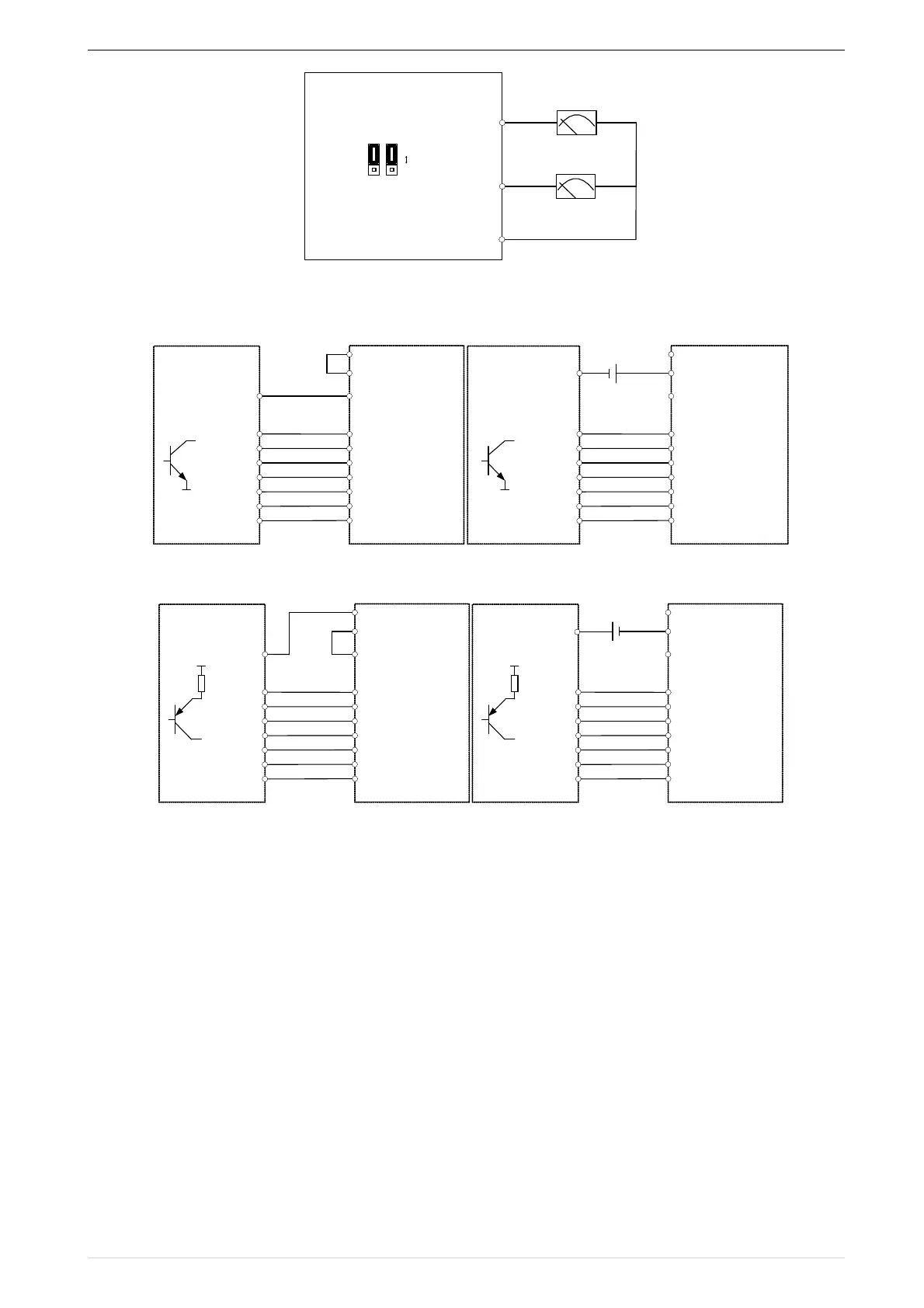
Digital input terminal instructions
ABy internal 24V with NPN mode BBy internal 24V with PNP mode
! !
CNPN mode uses external +24V power supply DPNP mode uses external +24V power supply
3-24 Switching Digital input terminal wiring diagram
Note
When using external power supply to drive DI terminal , the shorting tab(connector slip) between +24V and
PLC must be removed, otherwise the product will be damaged!
When using an external power supply, connect the negative terminal of the external power supply to COM when
using HDI, otherwise HDI is invalid!
Switch output terminal instructions
The multi-function output terminals DO1 and HDO can be powered by the internal +24V power supply of the
inverter or an external power supply. The wiring diagram is as follows:
Jumper
switch
Voltage output
Current output
6 (


51+
6
+42
D353 E
6
6
7C7
0
0
0
0
0 0 (
0 )
0
7
7
7
7
7)
7
7(
7 (


51+
7
+42
E353C F
7
7
D
0
0
0
0
0 0 (
0 )
0
)
(
7
346
7 (


51+
7
+42
E5356C F
7++
D
0
0
0
0
0 0 (
0 )
0
)
(
7++
7 (


51+
7
+42
E535C F
7++
D
0
0
0
0
0 0 (
0 )
0
)
(
7++
7
346
32

Table of Contents

Questions and Answers:

Question and Answer IconNeed help?

Do you have a question about the Danfoss VFD500 Series and is the answer not in the manual?

Danfoss VFD500 Series Specifications

General IconGeneral
BrandDanfoss
ModelVFD500 Series
CategoryDC Drives
LanguageEnglish

Related product manuals