Setting value depend on P03.16
P03.16 = 2, 0.00~600.00s;
P03.16 = 1, 0.0s~6000.0s;
P03.16 = 0, 0s~60000s
Setting value depend on P03.16
P03.16 = 2, 0.00~600.00s;
P03.16 = 1, 0.0s~6000.0s;
P03.16 = 0, 0s~60000s
Acceleration and deceleration curve, also known as "Ramp Frequency Generator (RFG)", is used to smooth the
frequency command. VFD500 supports the following acceleration and deceleration curve:
0: linear acceleration / deceleration
The output changes at a constant acceleration or deceleration. Acceleration time refers to the time from when the
inverter accelerates from zero to the reference frequency (selected by P03.15); deceleration time refers to the
time required to decelerate from the reference frequency to zero.
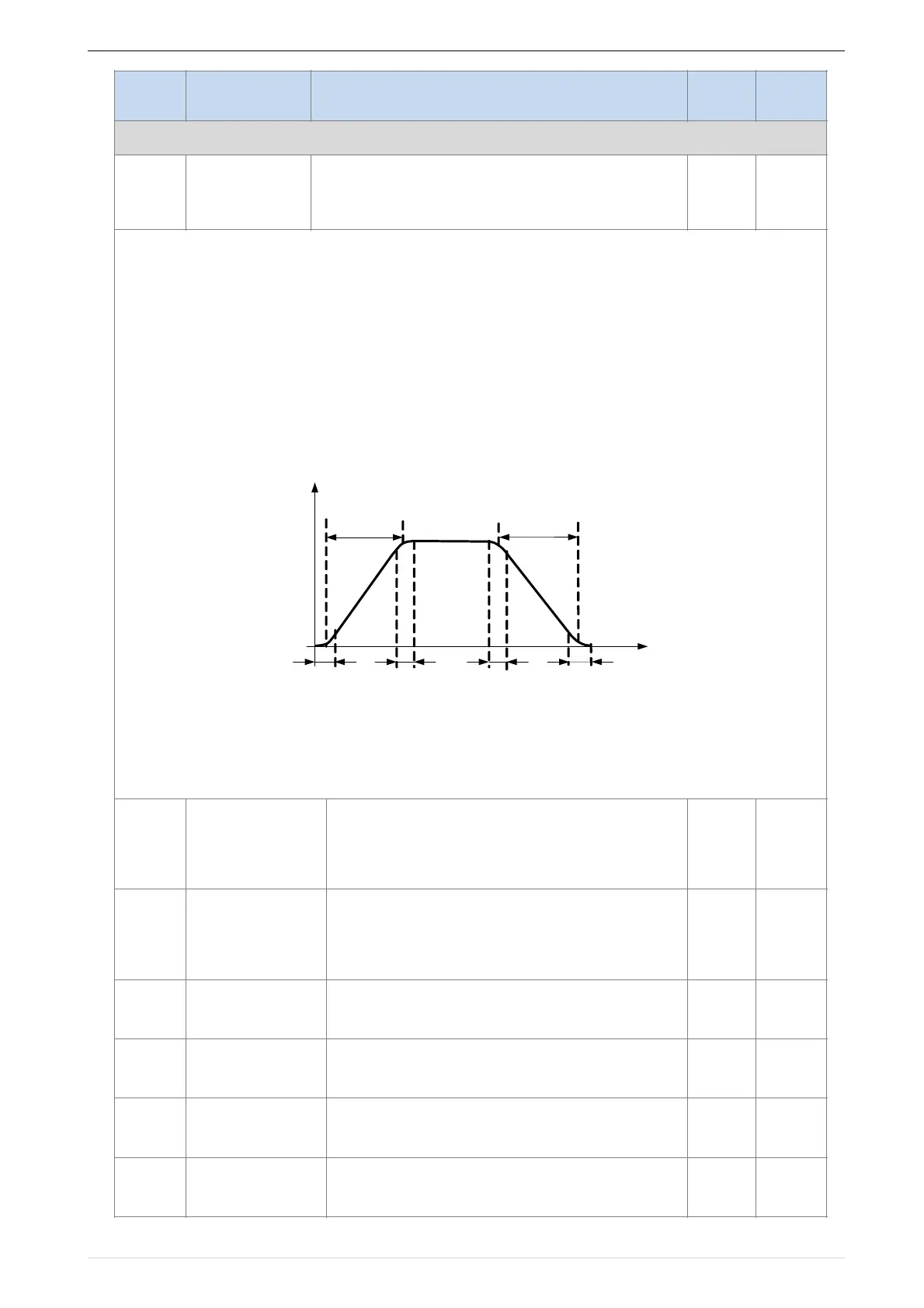
1: S curve method
This acceleration and deceleration curve acceleration "a" changes in a ramp, start and stop relatively flat.
Acceleration and deceleration process as shown below, Tacc and Tdec for the set acceleration and deceleration
time.
The acceleration and deceleration curve of the equivalent acceleration and deceleration time:
Acceleration time = Tacc + (Ts1 + Ts2) / 2
Deceleration time = Tdec + (Ts3 + Ts4) / 2
2: S curve method B
The time of this S-curve is defined as in the method A except that in the acceleration / deceleration process, if the
target frequency suddenly approaches or the acceleration / deceleration time changes, the S-curve is re-
planned. In addition, when the target frequency changes, the S Curves avoid "overshoot" as much as possible.
 Loading...

