VFD500 high performance vector control frequency inverter user manual Chapter 7 Selection guide of inverter
Accessory
.! !
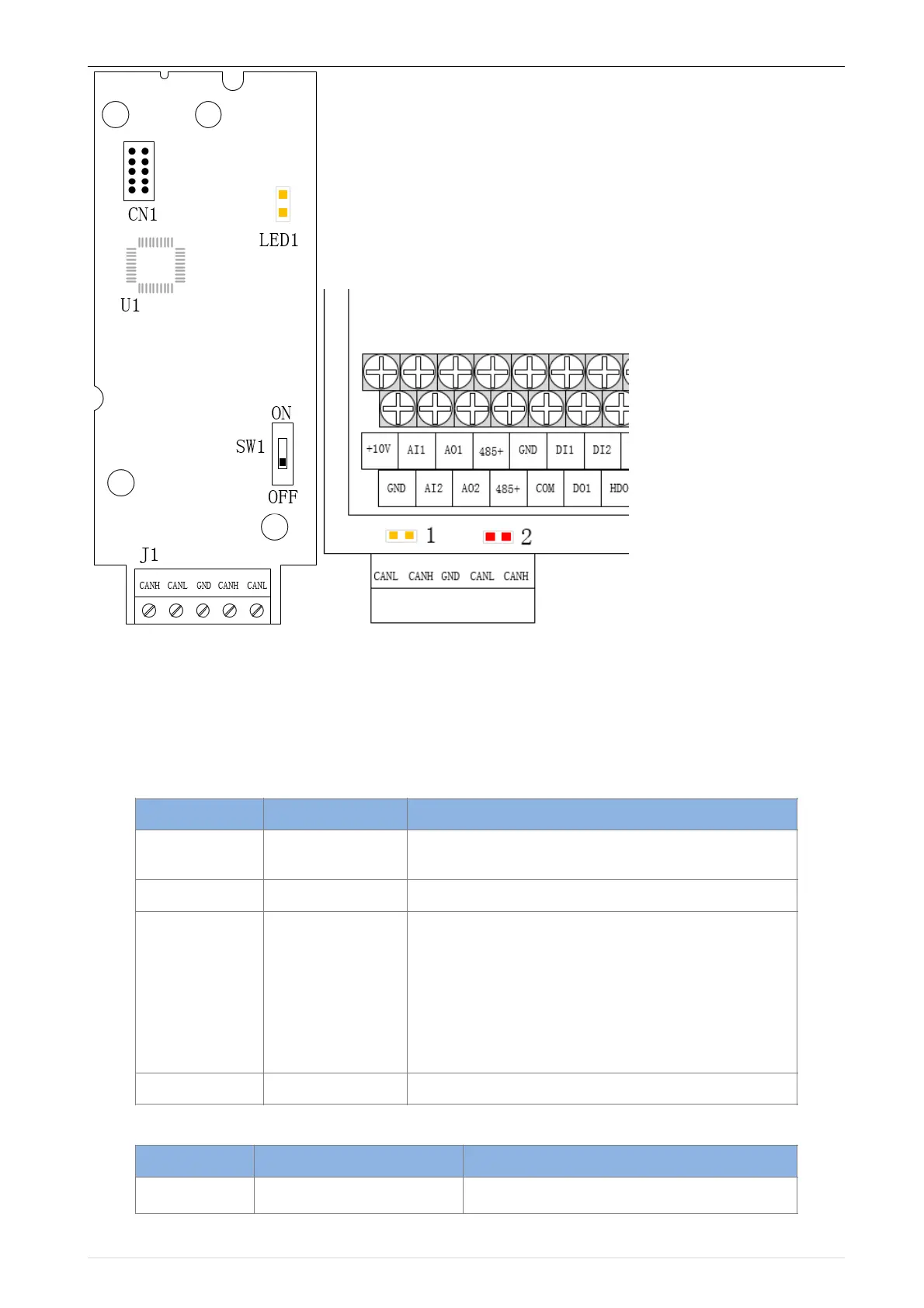
Figure 7-11 CANopen communication card and installation DiagramTable 7-12 CANopen
communication card hardware description
Table 7-9 Function description of J1 terminal block
CANopen bus terminal block, see description of
Table 7-9
Lights up to indicate normal power supply
Indicator light:
Yellow light (1)
Red light (2)
Working status and fault indication:
Yellow light (1) on: indicates normal operation
Yellow light (1) flash: indicates communication
initialization
Red light (2) on: indicates internal communication
failure
Red light (2) flash: indicates CANopen
communication failure or bus off
Terminating resistor for setting the CANopen bus
 Loading...

