! !
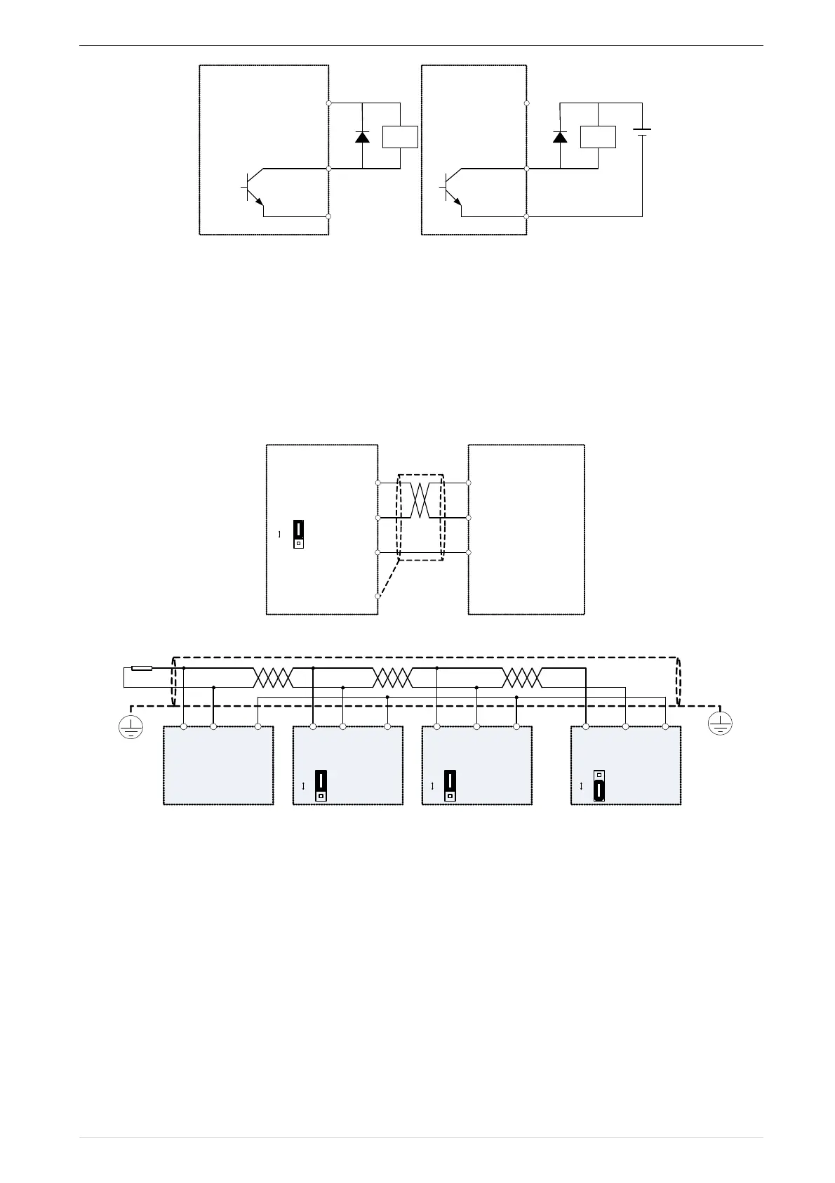
A、Use internal power supply B、Use external power supply
3-25 Switching digital output terminal wiring diagram
Note:
The multi-function terminal output is an open collector output with a maximum allowable current of 50mA. When
using the internal power supply, if the inductive load is driven, an absorption circuit such as an RC snubber circuit
or a freewheeling diode should be installed. When adding a freewheeling diode, be sure to confirm the polarity of
the diode, otherwise the product will be damaged. For external power supply, connect the negative terminal of the
external power supply to the COM terminal.
◆ 4 85Communication terminal instructions
!
3-26 Single inverter RS485 directly communicates with the host computer
!
3-16Multiple inverter RS485 is connected to the host computer for communication
 Loading...

