Appendix A Modbus communication protocol
VFD500 series of inverter provides RS485 communication on interface, and adopts MODBUS
communication protocol. User can carry out centralized monitoring through PC/PLC to get
operating
requirements and user can set the running command, modify or read the function codes, the
workingstate or fault information of frequency inverter by Modbus communication protocol.In addition
VFD 500can also be used as a host to broadcast with other VFD500 communication.
A.1 Protocl fomat
RS485 asynchronous half-duplex.
RS485 terminal default data format: 1-8-N-1 (1 start bit, 8 data bits, no parity, 1 stop bit), the default
baud rate: 9600bps. See parameter group set 30.
A.2 Message format
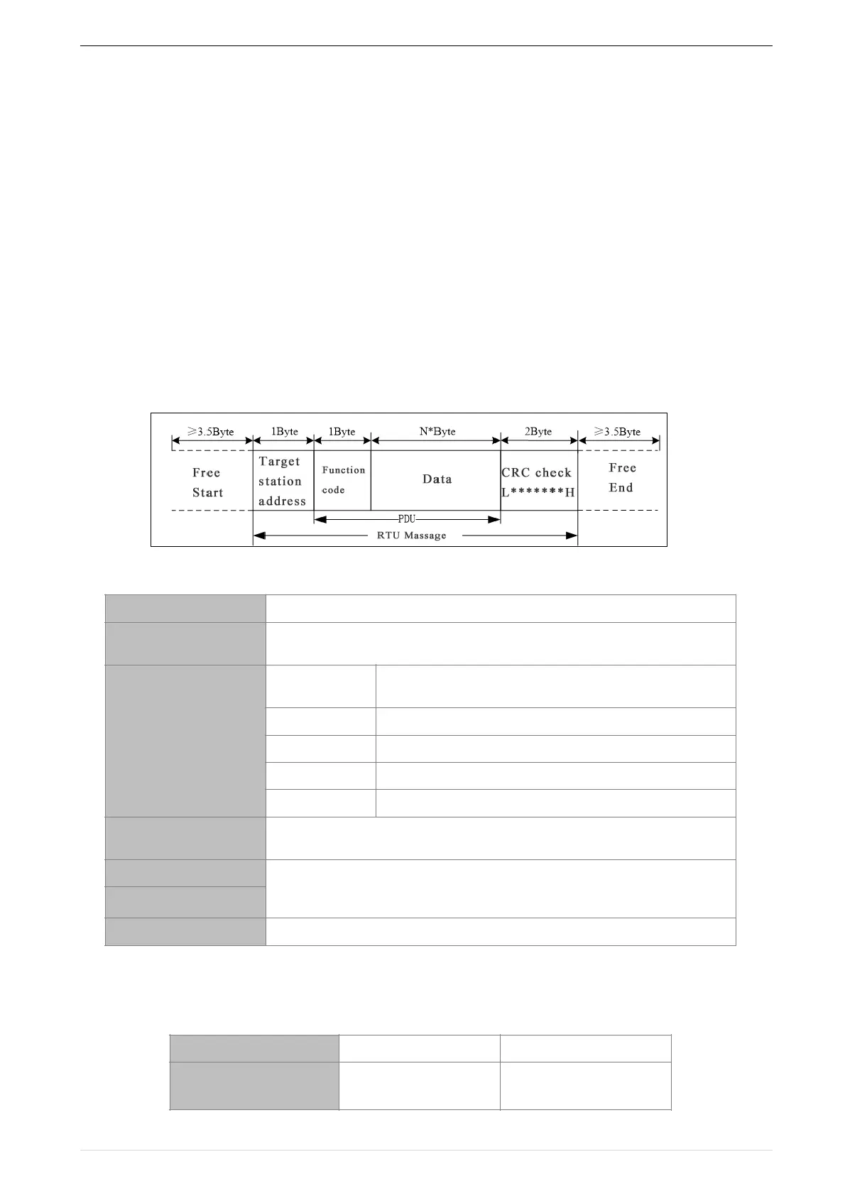
The VFD500 series inverter Modbus message includes the start sign, the RTU message, and the
end sign。
The RTU message includes the address code, the PDU (Protocol Data Uint, the protocol data
unit), and the CRC check. PDU includes the function code and the data section.
RTU frame format:
A.3 Command code instruction
A.3.1 Command code 0x03Read multiple registers or status words
●
Request PDU
Including the register address (2Byte), the number of registers n(2Byte)
and the register content (2nByte), etc.see A3 in detail
It indicates the replying data or the data waiting to
write-in. CRC 16 check value,During the transmission, high bit is put in
frontand low bit is at the back.see detail in A.5 Chapter
 Loading...

