EasyManuals Logo

Danfoss VFD500 Series User Manual

Danfoss VFD500 Series
137 pages
To Next Page IconTo Next Page
To Previous Page IconTo Previous Page
Page #78 background imageLoading...
Page #78 background image
VFD500 high performance vector control frequency inverter user manual Chapter 5 function code table
13 Group Motor 1 vector control
P13.00
Speed Proportional Gain
ASR_P1
0.1100.0
12.0
P13.01
Speed Integral Time
constant ASR_T1
0.001s30.000s
0.200s
P13.02
Speed Proportional Gain
ASR_P2
0.1100.0
10.0
P13.03
Speed Integral Time
constant ASR_T1
0.001s30.000s
0.500s
P13.04
ASR parameter Switching
frequency 1
0.00Hz ASR switching frequency 2(P13.05)
5.00Hz
P13.05
ASR parameter Switching
frequency 2
ASR switching frequency 1600.00Hz(P13.04)
10.00Hz
P13.06
Speed control torque limit
source selection
Unit’s digitElectric torque limit source #
0:Digital setting
1:Ai1
2:Ai2
3:AI3((IO expansion board)
4:AI4(IO expansion board)
5: HDI
6:Communication
Ten un itElectric torque limit source
Same as unit’digit
00
P13.07
Electric torque limit
0.0%300.0%
160.0%
P13.08
Upper limit of brake torque
0.0%300.0%
160.0%
P13.12
Torque current directives
filter time
Unitcurrent loop adjust cycle ,0100
2
P13.13
ACR Proportional Gain1
0.0110.00
0.5
P13.14
ACR Integral Time1
0.01300.00ms
10.00ms
By setting the speed factor and integration time of the speed regulator, you can adjust
Section vector controlled speed loop dynamic response characteristics. Increase the proportional gain and
reduce
The integration time can speed up the dynamic response of the speed loop, but the proportional gain is too large
Or the integration time is too small, it is easy to cause the system to oscillate, and the overshoot is too large.
Proportion increase
Too small is also likely to cause steady-state oscillations of the system, and there may be a speed difference.
!
PI has a close relationship with the inertia of the system. Adjust on the base of PI according to different loads to
meet various demands.
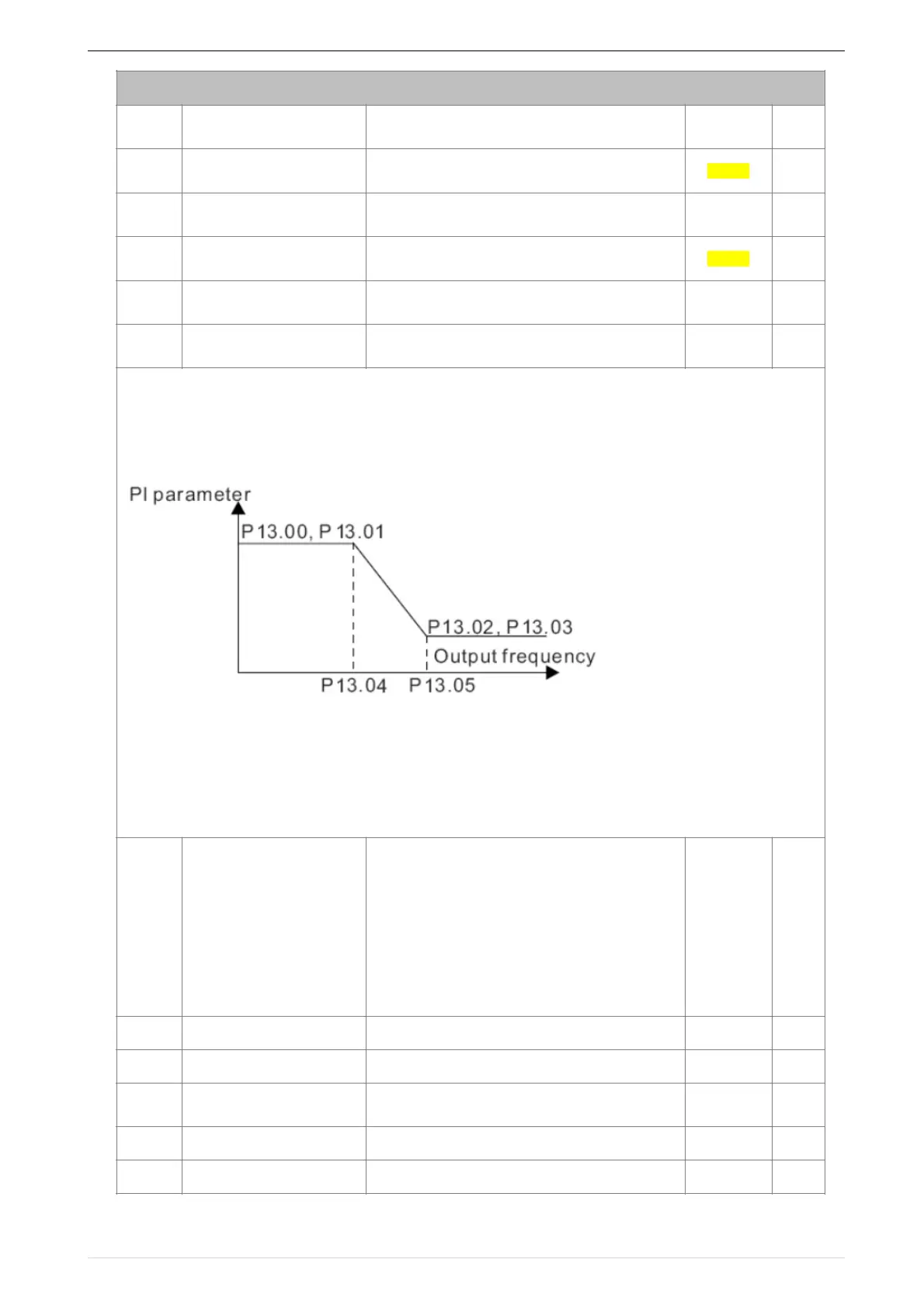
P13.00 and P13.01 are Speed adjuster parameter for low-speed use,scope of action from zero to P13.04
P13.02 and P13.03 are Speed adjuster parameter for high-speed use,scope of action from P13.05 to maximum
frequency
P13.04-P13.05 Two sets of parameter for linear tansitions
75

Table of Contents

Questions and Answers:

Question and Answer IconNeed help?

Do you have a question about the Danfoss VFD500 Series and is the answer not in the manual?

Danfoss VFD500 Series Specifications

General IconGeneral
BrandDanfoss
ModelVFD500 Series
CategoryDC Drives
LanguageEnglish

Related product manuals