EasyManuals Logo

Danfoss VFD500 Series User Manual

Danfoss VFD500 Series
137 pages
To Next Page IconTo Next Page
To Previous Page IconTo Previous Page
Page #29 background imageLoading...
Page #29 background image
VFD500 high performance vector control frequency inverter user manual Chapter3 Product appearance and wiring
!
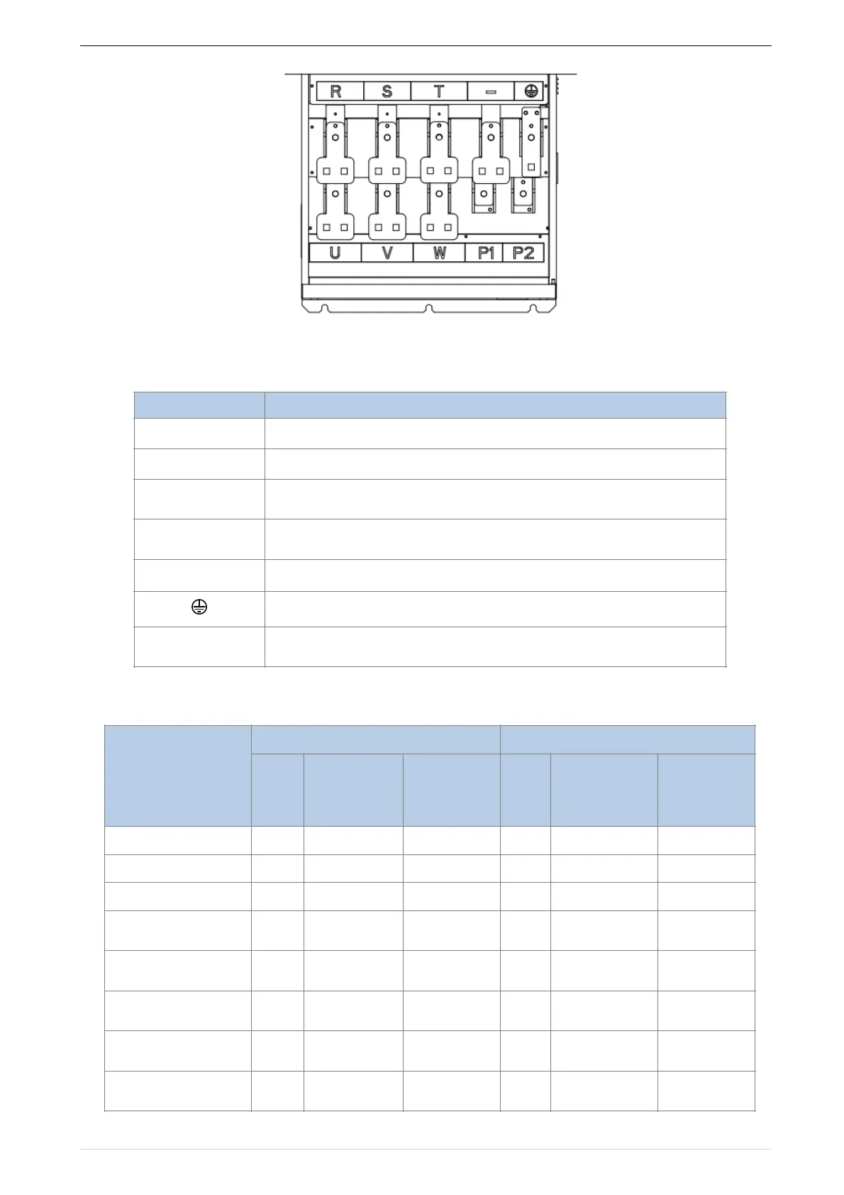
Figure 3-16 280kw-400kw Main Circuit Terminal Blocks
Table 3-17 Function description of the main circuit terminal of the inverter
3.2.3 Terminal screws and wiring specifications
Table 3-18 Main circuit cable and screw specifications
Terminal
Function instruction
RST
AC power input terminal, connect three-phase AC power
UVW
Inverter AC output terminal, connect three-phase AC motor
+-
The positive and negative terminals of the internal DC bus are connected to the
external brake unit or For common DC bus
P1P2
P1 and P2 are terminal to Connect DC reactor, short P1 to P2 when DC reactor
is not used (P2 is equivalent to "+" of DC bus)
+PB
Braking resistor connection terminal when built-in brake unit
Ground terminal, ground
EMCVDR
Safety capacitor and varistor grounding selection screw (SIZE A~SIZE C EMC
screw on the left side of the fuselage)
Model number
Power terminal
Ground terminal
Scre
w
Tightening
torqueN
m
Cable
diameterm
m
2
scre
w
Tightening
torqueNm
Cable
diameterm
m
2
VFD500-R75GT4B
M3
1.5
2.5
M3
1.5
2.5
VFD500-1R5GT4B
M3
1.5
2.5
M3
1.5
2.5
VFD500-2R2GT4B
M3
1.5
2.5
M3
1.5
2.5
VFD500-4R0G/
5R5PT4B
M3
1.5
4
M3
1.5
4
VFD500-5R5G/
7R5PT4B
M4
2
6
M4
2
6
VFD500-7R5G/
011PT4B
M4
2
6
M4
2
6
VFD500-011G/
015PT4B
M5
4
10
M5
4
10
VFD500-015G/
018PT4B
M5
4
10
M5
4
10
26

Table of Contents

Questions and Answers:

Question and Answer IconNeed help?

Do you have a question about the Danfoss VFD500 Series and is the answer not in the manual?

Danfoss VFD500 Series Specifications

General IconGeneral
BrandDanfoss
ModelVFD500 Series
CategoryDC Drives
LanguageEnglish

Related product manuals