VFD500 high performance vector control frequency inverter user manual Chapter 5 Function code
Chapter 5 Function Code Table
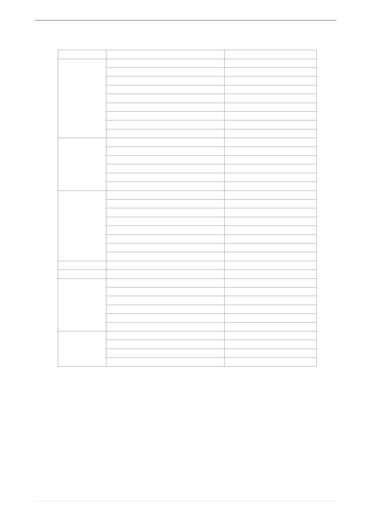
The following is the VFD500 parameter distribution list:
Term Description:
The parameter is also called function code; the operation panel is also called the keyboard.
Due to usage habits, different terms may be used in different places in this manual, but all refer to the same
content.
Symbol Description:
"☆" means that the setting value of this parameter can be changed when the inverter is stopped or running.
"★" means that the setting value of this parameter can not be changed when the inverter is running.
"●" indicates that the value of this parameter is the actual test record value, which can not be changed%
01:Frequency source selection
04: Analog and pulse input
05:Analog and pulse output
06:Multi-function Digital input (DI)
07: Multi-function Digital output(DO)
08:Digital Output setting
12:Motor1 VFcontrol parameter
13:Motor1 Vector controlparameter
D i s p l a y a n d
protection
20:User-defined parameters
22:AC Drive configuration
23:Drive protection function setting
24:Motor protection parameter
25:Fault tracking parameter
26:Fault recording parameter
43:Programmable delay unit
44:Comparator and logic unit/controller
60:Motor2 basic parameter
62:Motor2 VF control parameter
63:Motor2 vector control parameter
 Loading...

