VFD500 high performance vector control frequency inverter user manual Chapter 4 Operation and display
4.2 Display hierarchy and menu mode
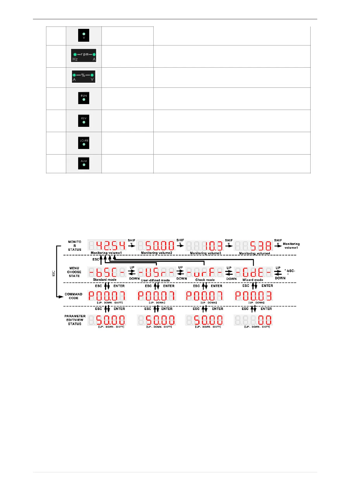
VFD500 digital keyboard display is divided into four layers, from top to bottom are: monitoring status, menu
mode selection status, function code selection status, parameter editing / viewing status, as shown in Figure 4-2. In
the menu mode selection status, press 【UP】 or 【DOWN】 key to select menu mode, press 【ENTER】 to
enter the selected menu mode, the following describes several menu modes:
4-2Keyboard operation diagram
◆ Standard mode(-bSC-)
If visiting access (P00.01) is standard, all the function codes mentioned in this manual are accessible.
If visiting access (P00.01) is the end user (in the state of user password lock), then only some function code can be
accessed.
◆ User-difined mode(-USr-)
In this menu mode, only 20 user-defined parameters defined are displayed.
◆ Verify mode(-vrF-)
In this menu mode, only parameters that differ from the factory settings are displayed。
◆ Guide mode(-GdE-)
When users first use the inverter, can guide the user to complete a simple trial run。
Indicator
light:HZ+A(rpm/
minute)
When Hz" and "A" are lit at the same time, the unit of the
currently displayed parameter is "RPM PER MINUTE
I n d i c a t o r
light:A+V(%)
When "A" and "V" are lit at the same time, the unit of the
currently displayed parameter is "percent".
• Off: indicates a stop condition.
• On: indicates inverter is running.·
Blinking: Deceleration stopped.
• Used to indicate the sign of the variable when the LED is
displaying one of the variables listed in 27.02;
• In other cases the sign of the output frequency is indicated.
• Off: The command source is the keyboard.
• On: The command source is terminal.
• Blinking: The command source is communication.
• When it is on, the drive is faulty.