EasyManuals Logo

Danfoss VFD500 Series User Manual

Danfoss VFD500 Series
137 pages
To Next Page IconTo Next Page
To Previous Page IconTo Previous Page
Page #122 background imageLoading...
Page #122 background image
Chapter 7 Selection guide of inverter Accessory VFD500 high performance vector control frequency inverter user
manual
7.2 PG card type
The optional PG card and supported encoders for the VFD500 are shown in the table below.
Chart 7-3 PG type view chart
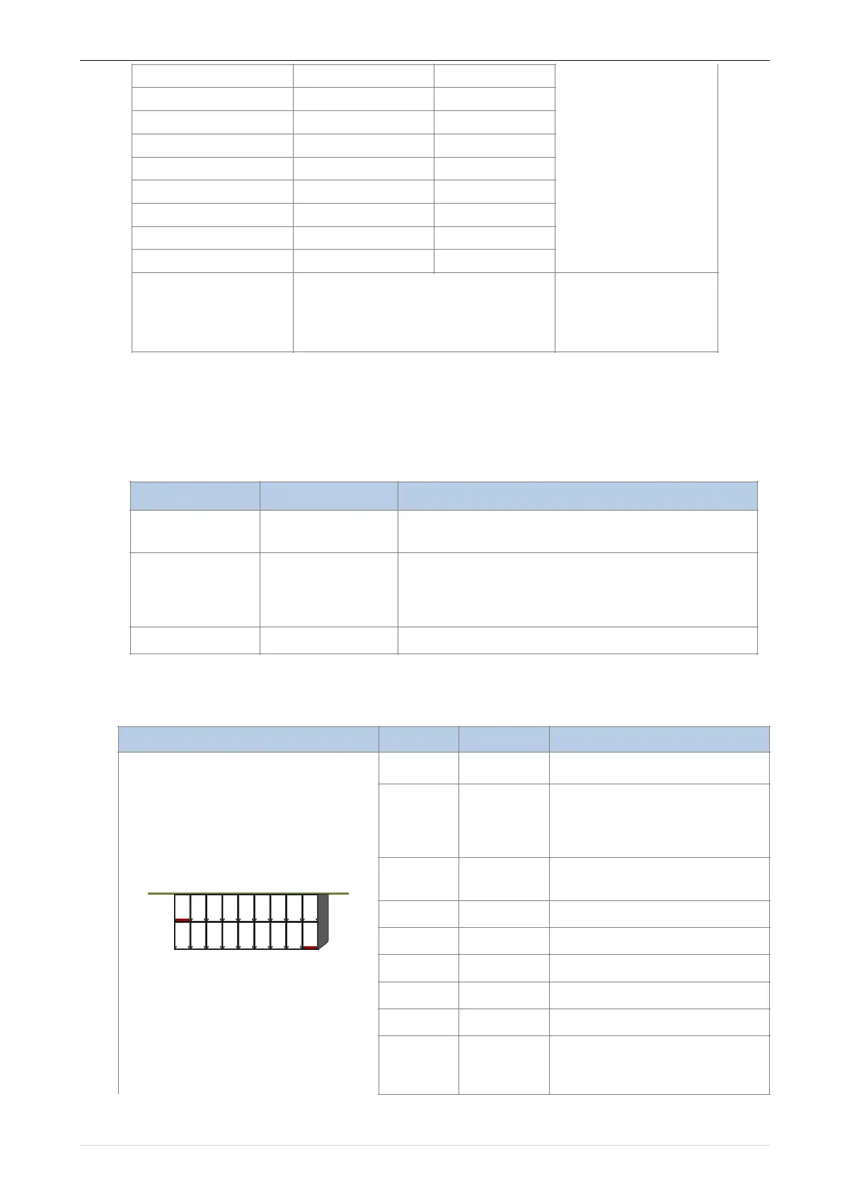
1INCREMENTAL PG
Chart 7-4 Incremental encoder PG card (VFD500-PG-INC1) port definition
VFD500-011G/015PT4B
1.2KW
25Ω
Built-in as option
VFD500-015G/018PT4B
1.5KW
25Ω
VFD500-018G/022PT4B
2.0KW
18Ω
VFD500-022G/030PT4B
2.5KW
18Ω
VFD500-030G/037PT4
3.0KW
12Ω
VFD500-037G/045PT4
3.7 KW
15Ω
VFD500-045G/055PT4
4.5 KW
8Ω
VFD500-055G/075PT4
5.5 KW
6Ω
VFD500-075G/090PT4
7.5 KW
6Ω
VFD500-090G/110PT4
VFD500-710GT4
As per actual load and braking power
external
Model
name
USAGE
VFD500-PG-INC1
INCREMENTAL PG
open collector type, push-pull output type, differential
output type encoder.
VFD500-PG-INC2
Incremental
encoder PG card
with Frequency
division
open collector type, push-pull output type, differential
output type encoder.
Frequency division range: 0~63
VFD500-PG-RT1
RESOLVER PG
Rotary transformer encoder
Pin number diagram
Pin number
Name
Usage
110
PE
Shield terminal
211
VCC
Power output for powering the
encoder
5V ± 2%, maximum 200mA
12V±5%, maximum 200mA
312
GND
Power supply common terminal
and signal
4
/Z
Encoder Z-signal
5
Z
Encoder Z+signal
6
/B
Encoder B-signal
7
B
Encoder B+signal
8
/A
Encoder A-signal
9
A
Encoder A+signal
119

Table of Contents

Questions and Answers:

Question and Answer IconNeed help?

Do you have a question about the Danfoss VFD500 Series and is the answer not in the manual?

Danfoss VFD500 Series Specifications

General IconGeneral
BrandDanfoss
ModelVFD500 Series
CategoryDC Drives
LanguageEnglish

Related product manuals