VFD500 high performance vector control frequency inverter user manual Chapter 5 function code table
Accel and Decel
time unit
selection
Quickstop
deceleration time
Switchingfrequen
cy 1 in
acceleration time
0.00Hz~maximum frequency(P01.06)
Switchingfrequen
cy 1 in
deceleration time
0.00Hz~maximum frequency(P01.06)
Forward/reverse
Dead band time
0.00s~30.00s Waiting time for zero speed during forward
and reverse switchover
04 Group Analog and Pulse input
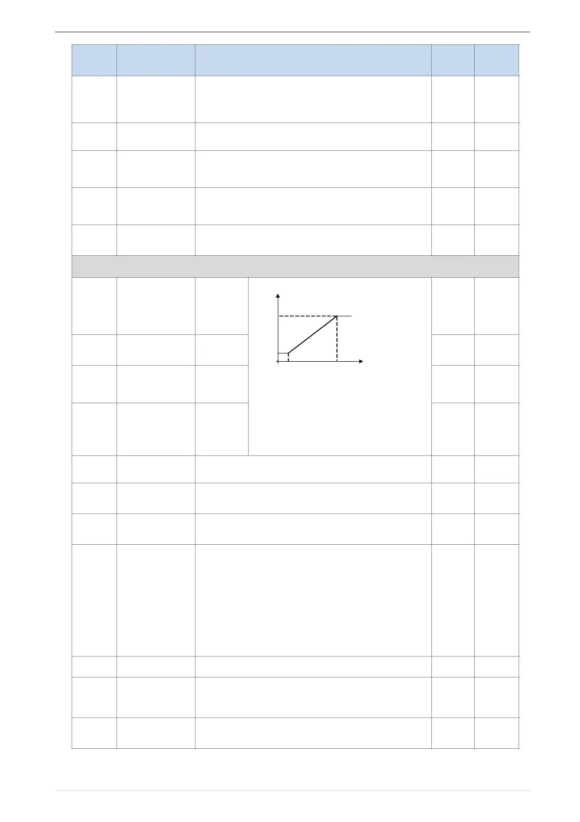
Minimum input
pulse frequency
Maximum input
pulse frequency
Setting
Corresponding to
Minimum input
Setting
Corresponding to
maximum input
0.00kHz~50.00kHz(it is used to check HDI pulse input
frequency)
-100.0%~100.0%(it is used to View the output of the HDI
mapping curve)
Unit’s:AI curve selection
0:curve A
1:curve B
2:Curve C
3:Curve D
Ten’ un it:when input signal lower than minimum input #
0:equal to minimum input
1:equal to 0.0%
0.00V~10.00V ( it is used to view the port voltage of AI1.
When AI1 is a current type (0~20mA) input, multiplying this
value by 2 is the input current (mA) of the AI1 port.)
-100.0%~100.0%(It is used to view the output of the AI1
mapped curve)
P04.01
P04.03
HDI input frequency
Corresponding setting
P04.00
P04.02
 Loading...

