VLT
®
5000 FLUX
sec. = OFF means that the time is infinite; however,
the thermal monitoring will still be active.
417 Speed PID proportional gain
(SPEED PROP GAIN)
Value:
0.000 (OFF) - 0.150
✭ 0.015
Function:
Speed Proportional gain indicates how many
times the error (deviation between the feedback
signal and the set-point) is to be amplified. Used
together with Speed con trol, closed loop and Speed
control, open loop (parameter 100).
Description of choice:
Quick control is obtained at high amplification, but
if the amplification is too high, the process may
become unstable in the case of overshoot.
418 Speed PID integral time
(SPEED INT. TIME)
Value:
2.00 - 19.999.99 ms (20.000 = OFF)
✭ 200 ms
Function:
Speed integral time determines how long time the
internal PID controller takes to correct the error.
The greater error, the quicker the gain increases.
The integral time results in a delay of the signal
and therefore a dampening effect. Used together
with Speed control, closed loop and Speed
control, open loop(parameter 100).
Description of choice:
Quick control is obtained through a short integral time.
However, if this time is too short, it can make
the process unstable.
If the integral time is long, major deviations
from the required reference may occur, since
the process regulator will take long to regulate
if an error has occurred.
421 SPEED FILT. TIME
Value:
1-500 ms
✭ CL: 5 ms / OP: 20 ms
Function:
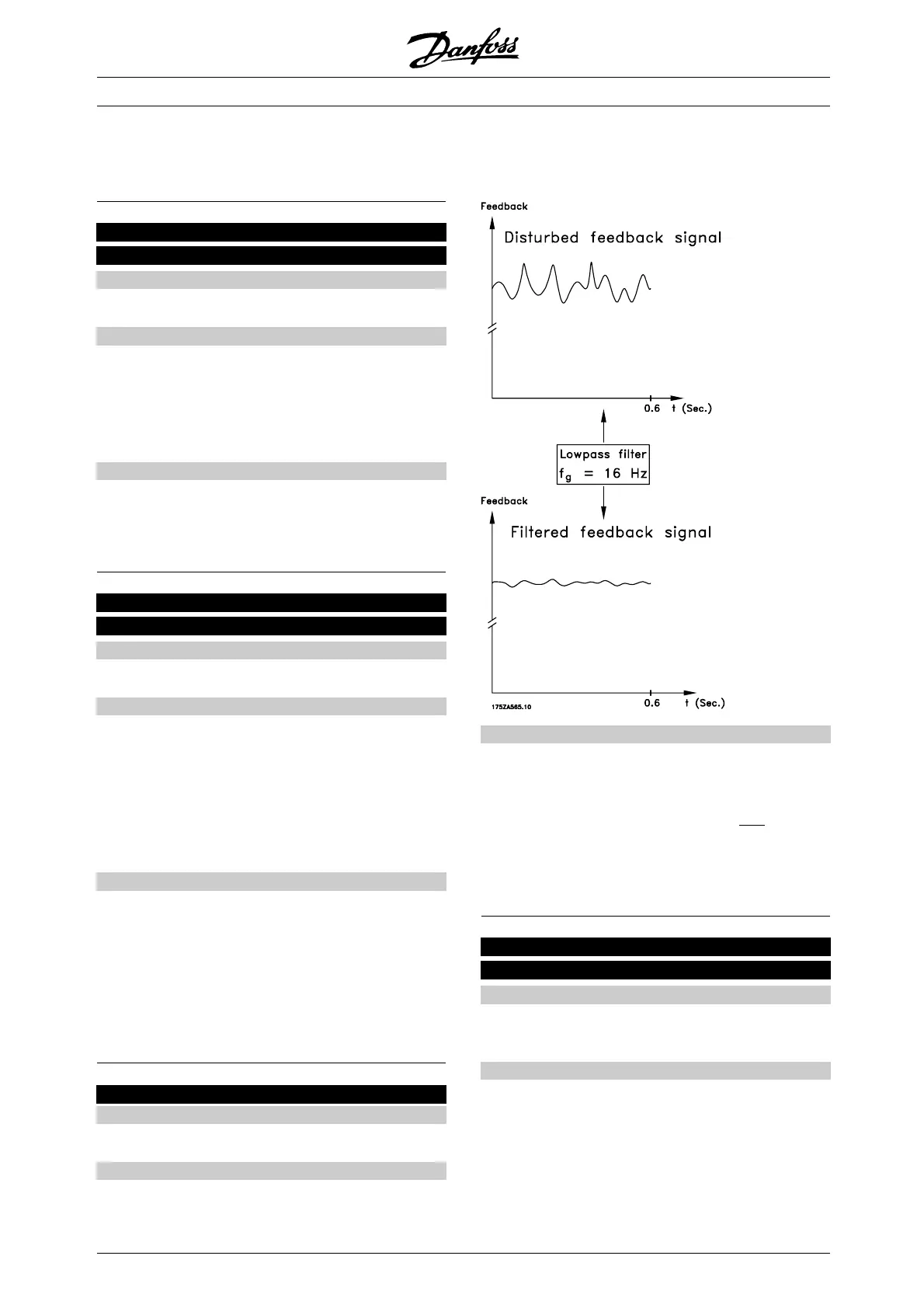
Oscillations on the feedback signal are dampened
by a lowpass filter and the resolution on speed
measurement is increased. This is necessary for the
Flux Vector control to function properly. TheSpeed
Filter Time is used with Speed Control, Closed Loop.
Description of choice:
Ifatimeconstant(τ) eg. of 10 ms is progr
ammed, the
cut-off frequency for the lowpass filter will be 1/0.01 =
100 RAD/sec., corresponding to (100/2 x π) = 16.0
Hz. This means that the PI regulator w
ill o
nly regulate
a feedback signal that varies by a frequency of less
than 16.0 Hz. If the feedback signal varies by a higher
frequency than 16.0 Hz, the PI r
egulator will not react.
445 Flying start
(FLYING START)
Value:
✭Off (DISABLE)
[0]
On (ENABLE)
[1]
Function:
This function makes it possible to catch spinning motor,
which is spinning freely because of a mains drop-out.
✭
= factory setting. () = display text [] = value for use in communication via serial communication port
MG.55.A6.02 - VLT is a registered Danfoss trademark
106

 Loading...