VLT
®
5000 FLUX
All about FCD
300
Terminal 37 is a "Hardware Coast" input function
for disabling the output stages (inverter). Terminal
37 cannot be disabled, handled or adjusted by
any parameters. Terminal 37 must be pulled up
to 24 V DC for the unit to work.
Installation of Control Cables
Tightening-up torque: 0.22 - 0.25 Nm
Screw size: M2
Screw driver type: 0.4 x 2.5 x 80 mm
See Earthing of Braided Screened/Armoured
Control Cables for correct earthing.
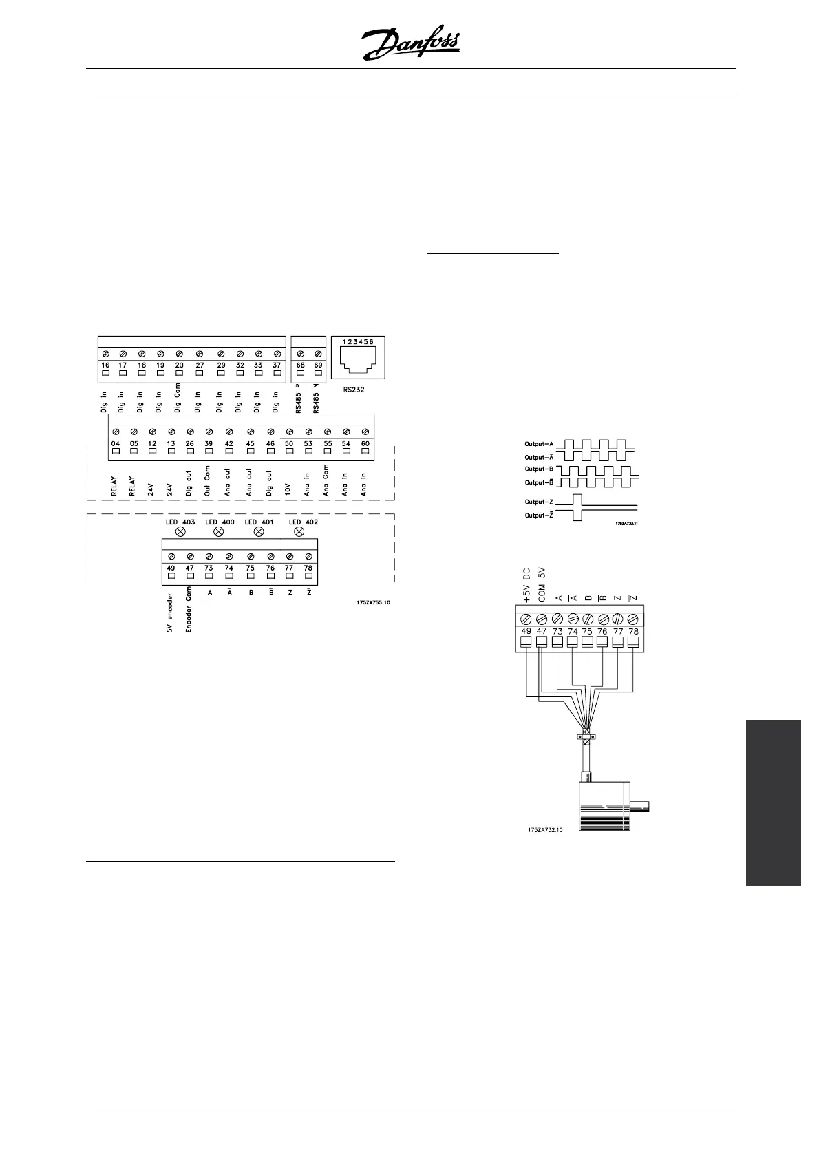
LEDs on encoder board:
When all LEDs are ON the connection to encoder
and encoder condition are OK.
LED 403 OFF: 5 V supply missing
LED 400 OFF: Channel A or inv. A missing
or shortcircuited
LED 401 OFF: Channel B or inv. B missing
or shortcircuited
LED 402 OFF: Channel Z or inv. Z missing
or shortcircuited.
■ Feedback System
The feedback system is necessary when the drive is
set to closed loop operation (Parameter 100 [1] or [5] ).
The VLT 5000 Flux accepts incremental encoders
as feedback system from motor.
C
onnection of encoder
VLT 5000 Flux supports most types of 4 channel + zero
pulse incremental encoders as feedback device.
Power
supply
5 V DC max 250 mA
(Encoder power consumption max
0.75 watt).
Max cable
length
(according to RS422 spec) < 150 m
If longer cables are used, please
contact Danfoss Drives.
Typical impulse pattern from an incremental encoder
Basic encoder connection
MG.55.A6.02 - VLT is a registered Danfoss trademark
33

 Loading...