VLT
®
5000 FLUX
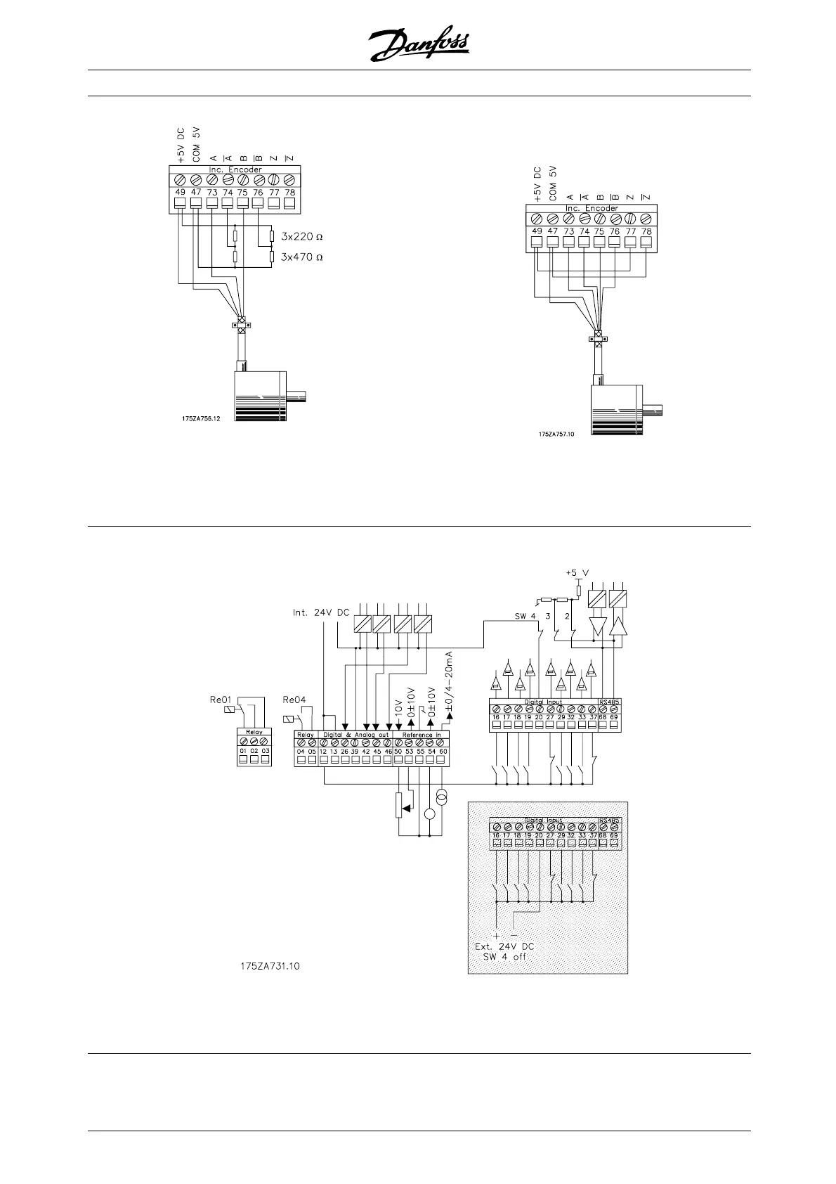
If the encoder has no inverted outputs, the encoder
cable can only have a length of max 3 meter. The
encoder input must then be terminated as shown.
The encoder surveillance circuit must be switched
off in parameter 350 [0].
If the encoder has no zero pulse, and the encoder
monitor is enabled (parameter 350), the inputs
77 and 78 must be terminated.
■ Electrical installation
Regarding programming of the digital and analog
inputs and outputs, see parameter group 300.
■ Bus connection RS 485
The serial bus connection is connected to terminals
68/69 of the frequency converter (signals P and N) in
accordance with the RS 485 (2-wire) norm. Signal
P is the positive potential (TX+,RX+), while signal
N is the negative potential (TX-,RX-).
MG.55.A6.02 - VLT is a registered Danfoss trademark
34

 Loading...