VLT
®
5000 FLUX
All about FCD
300
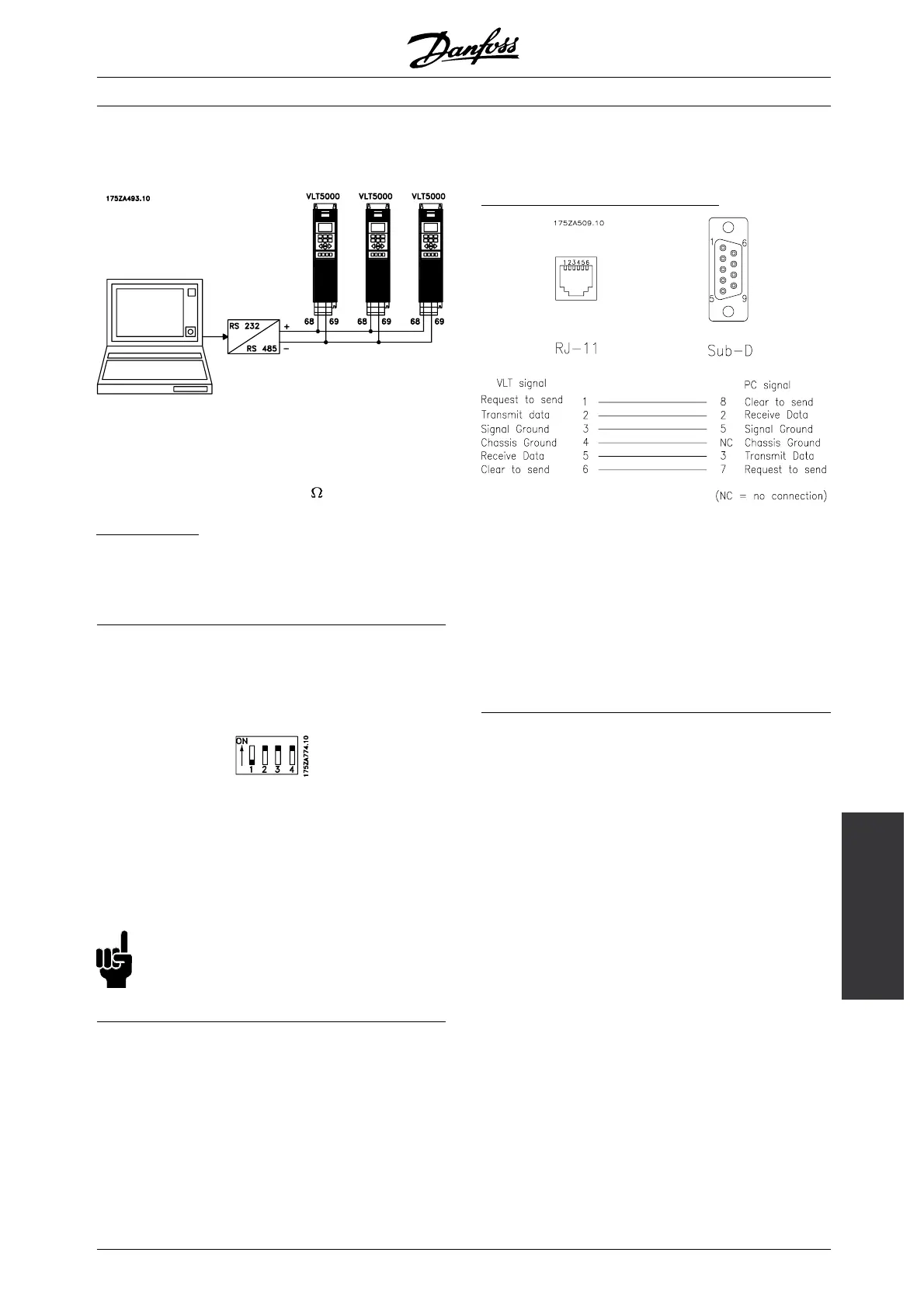
If more than one frequency converter is to be connected
to a given master, use parallel connections.
In order to avoid potential equalizing currents the
circuit driving terminals 68 and 69 are connected to
the VLT chassis ground via a 100
resistor.
B
us termination
The bus must be terminated by a resistor network at
both ends. For this purpose, set switches 2 and 3
on the control card for "ON", see Switches 1-4.
■ DIP Switches 1-4
The DIP switch is located on the control card.
It is used for serial communication, terminals 68 and 69.
The switching position shown is the factory setting.
Switch 1 must always be open (off).
Switches 2 and 3 are used for terminating an RS
485 interface, serial communication.
Switch 4 is used for separating the common potential
for the internal 24 V DC supply from the common
potential of the external 24 V DC supply.
NB!:
Please note that when Switch 4 is in position
"OFF", the external DC supply is galvanically
isolated from the frequency converter.
■ Bus Connection RS 232
The purpose of the RS 232 is to enable communication
between a PC and a frequency converter. With this
communication it is possible to monitor, programme
and control the frequency converter.
However, it is not possible to use the RS 232
concurrently with the RS 485. When using one
of the buses, the other must be disconnected,
ie. when using eg. the RS 232, the RS 485 plug
must be removed from the board.
H
ardware connection of the RS 232:
Pin 1 is connected to pin 6 on the control card,
which results in the PC receiving a "Clear to Send"
when it sends a "Request to Send".
Pin1istheleftterminalonRJ-11.
Communication cable with an RJ-11 male plug in both
ends and an adaptor between RJ-11 and Sub-D 9
connector (for PC connection) (175Z3217).
MG.55.A6.02 - VLT is a registered Danfoss trademark
35

 Loading...