Digital input/output terminals
Terminal Parameter Default
setting
Description
27 Parameter 5-12
Terminal 27
Digital Input
[2] Coast
inverse
For digital input or
output. Default
setting is input.
29 Parameter 5-13
Terminal 29
Digital Input
[14] JOG
20 – – Common for digital
inputs and 0 V
potential for 24 V
supply.
37 – STO When not using the
optional STO feature,
a jumper wire is
required between
terminal 12 (or 13)
and terminal 37. This
set-up allows the
drive to operate with
factory default
programming values.
Table 5.2 Digital Input/Output Terminal Descriptions
Analog input/output terminals
Terminal Parameter Default
setting
Description
39 – – Common for analog
output.
42 Parameter 6-50
Terminal 42
Output
[0] No
operation
Programmable analog
output. 0–20 mA or
4–20 mA at a
maximum of 500 Ω.
50 – +10 V DC 10 V DC analog
supply voltage for
potentiometer or
thermistor. 15 mA
maximum.
53 Parameter
group 6-1*
Analog Input 1
Reference Analog input. For
voltage or current.
Switches A53 and
A54 select mA or V.
54 Parameter
group 6-2*
Analog Input 2
Feedback
55 – – Common for analog
input.
Table 5.3 Analog Input/Output Terminal Descriptions
5.9.3 Wiring to Control Terminals
The control terminals are located near the LCP. The control
terminal connectors can be unplugged from the drive for
convenience when wiring, as shown in Illustration 5.35.
Either solid or exible wire can be connected to the
control terminals. Use the following procedures to connect
or disconnect the control wires.
NOTICE
Minimize interference by keeping control wires as short
as possible and separate from high-power cables.
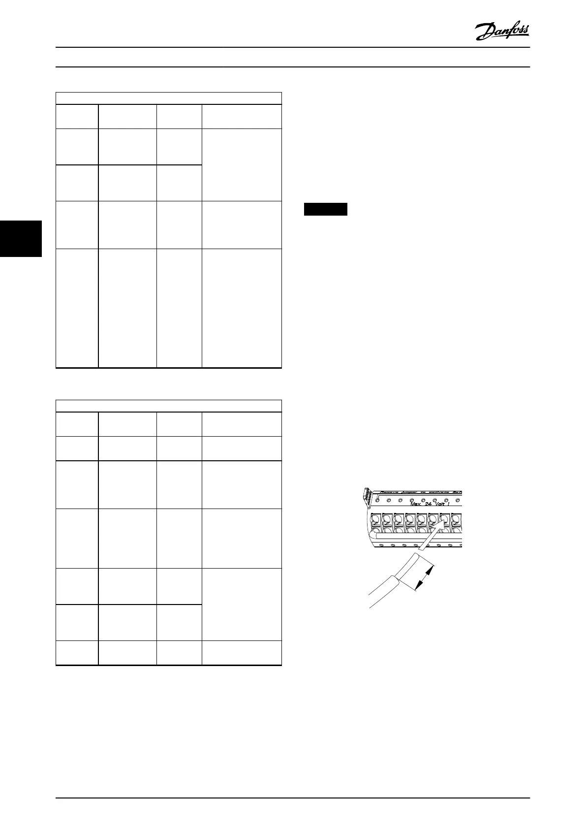
Connecting wire to control terminals
1. Strip 10 mm (0.4 in) of the outer plastic layer
from the end of the wire.
2. Insert the control wire into the terminal.
•
For a solid wire, push the bare wire into
the contact. See Illustration 5.37.
•
For a exible wire, open the contact by
inserting a small screwdriver into the
slot between the terminal holes and
push the screwdriver inward. See
Illustration 5.38. Then, insert the stripped
wire into the contact, and remove the
screwdriver.
3. Pull gently on the wire to ensure that the contact
is rmly established. Loose control wiring can be
the source of equipment faults or reduced
performance.
e30bg283.10
10 mm (0.4)
12 13 18 19 27 29 32 33
Illustration 5.37 Connecting Solid Control Wires
Electrical Installation VLT® AQUA Drive FC 202
64 Danfoss A/S © 09/2018 All rights reserved. MG21A502
55

 Loading...


